diy solar

diy solar

Ryobi Zero-Turn Mower SLA to LiFePo4 Conversion - (Updated - Build Complete With Pics!)

Update - I charged each battery up separately and reached full charge voltage. I then got a simple battery load tester and currently testing draining each battery separately to validate their charge capacity. So far the "weak" battery in the series string that had much lower voltage than the other three that were basically the same reported tested to have 105Ah capacity for the vs the listed 100Ah. The results showed 1311Wh vs the listed 1280Wh. So based on those results the 12v battery actually had more usuable capacity than listed. Currently testing the other three batteries.

The additional parts for testing are also showing up. I'm not looking to invest the money in a drop-in 48v pack so looking to do the least invasive yet most easily supported model to keeping these four 12v batteries balanced without having to open up the mower and pull the battery tray out to access the terminals. My leading idea is to:
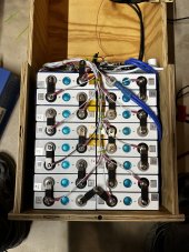
1. Connect the four 12v batteries in series using the original wiring.
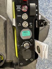
2. Install a 12v voltmeter directly to each battery with an included switch in case I wanted to turn off the always-on voltmeter display. This way I can open up the top access cover under the seat and see the state of each battery.
3. Install an Anderson SB50 adapter to each 12v battery so that I can open up the top access cover and top off each battery with a single 12v charger without needing to open up the mower.

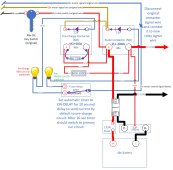
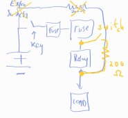
Here is the picture install approach I'm looking to do. Any concerns or changes I should be making?

View attachment 141031
I'm about to start my conversion this week(end)...

I've replaced my SLA's twice and agree it's a PITA getting the batteries loaded/unloaded. I'd like to have a similar setup as yours. Do you have a link to the volt meter display and the anderson connectors? What guage wiring and ring terminals are you going to use?

Replaced the round stock battery meter with this one from AiLi/Camway on amazon: here
You have to widen the hole for the original monitor some with a file/dremel or large step bit to fit the new monitor.
If you decide to attach the new monitor shunt directly to the battery terminal you'll need at least a M8x30mm 1.25 stainless steel bolt to make the connection.

All of the ring connectors are M8 (or 5/16).

Most of the batteries will look for you to use 6awg wire for your actual load current. Shouldn't be an issue if you're using 4 drop-in 12v batteries since you can reuse the original SLA battery wiring in that case. Most of the chargers don't put out high amps, so you can get away with 10awg wire for charging.
I bought some 10-12awg SB50 Anderson plugs from Amazon: here

If you needed a quick SB50 10awg adapter with ring bolts you can get a pair at a decent price on Amazon: here

Because of the voltage drift on my batteries I am going to try these voltmeters attached to each battery since they can be manually calibrated. Bought them off Amazon: here

The nicer looking voltmeters I originally bought had some pretty inconsistent readings even though they looked nicer. I may explore it further, since they are easier to install, but no way to calibrate them. Bought from amazon here.

Depending on the batteries you get, you may want to charge them up then run a load test to validate the capacity. I had good luck with this one recommended from Will Prowse on his youtube channel that I bought from Amazon here.

For other cables and adapters of different lengths and gauges with different Anderson plugs I found a good and cheap source to be from BatteryCablesUSA.com such as see here.

I bought some simple toggle switches to turn off my voltmeters to avoid any trickle drain on the batteries off Amazon here.

If you need any decent extra lengths of wiring at different gauges off Amazon here

I have been trying to reuse the existing ezgo tri plug with the mower with Dakota Lithium 48v charger. I didn't want to cut off my original charger handle so I bought this pre-made set on Amazon and simply added a 10awg SB50 connector to it. Here is the ezgo charger handle here.

I'm sure we will all look forward to hearing what results you have with your conversion and which batteries you went with. In retrospect I wish I had just paid more and bought a single 48v pack vs the four 12v batteries and just used some kind of cargo tiedown strap to secure the 48v to the battery tray. At this point it isn't worth investing that much more into the mower vs just getting a newer generation battery mower from one of the manufacturers. The "science experiment" part of this conversion has lost its appeal vs the cost involved and the need to have a functioning mower!

Good luck!
 
I thought a lithium zero turn was for sale at my Home Depot, but so far, I’ve only seen the SLA version for sale.
I have seen the review and commercials for the 80V lithium one, but haven’t seen it for sale anywhere.
 
Replaced the round stock battery meter with this one from AiLi/Camway on amazon: here
You have to widen the hole for the original monitor some with a file/dremel or large step bit to fit the new monitor.
If you decide to attach the new monitor shunt directly to the battery terminal you'll need at least a M8x30mm 1.25 stainless steel bolt to make the connection.

All of the ring connectors are M8 (or 5/16).

Most of the batteries will look for you to use 6awg wire for your actual load current. Shouldn't be an issue if you're using 4 drop-in 12v batteries since you can reuse the original SLA battery wiring in that case. Most of the chargers don't put out high amps, so you can get away with 10awg wire for charging.
I bought some 10-12awg SB50 Anderson plugs from Amazon: here

If you needed a quick SB50 10awg adapter with ring bolts you can get a pair at a decent price on Amazon: here

Because of the voltage drift on my batteries I am going to try these voltmeters attached to each battery since they can be manually calibrated. Bought them off Amazon: here

The nicer looking voltmeters I originally bought had some pretty inconsistent readings even though they looked nicer. I may explore it further, since they are easier to install, but no way to calibrate them. Bought from amazon here.

Depending on the batteries you get, you may want to charge them up then run a load test to validate the capacity. I had good luck with this one recommended from Will Prowse on his youtube channel that I bought from Amazon here.

For other cables and adapters of different lengths and gauges with different Anderson plugs I found a good and cheap source to be from BatteryCablesUSA.com such as see here.

I bought some simple toggle switches to turn off my voltmeters to avoid any trickle drain on the batteries off Amazon here.

If you need any decent extra lengths of wiring at different gauges off Amazon here

I have been trying to reuse the existing ezgo tri plug with the mower with Dakota Lithium 48v charger. I didn't want to cut off my original charger handle so I bought this pre-made set on Amazon and simply added a 10awg SB50 connector to it. Here is the ezgo charger handle here.

I'm sure we will all look forward to hearing what results you have with your conversion and which batteries you went with. In retrospect I wish I had just paid more and bought a single 48v pack vs the four 12v batteries and just used some kind of cargo tiedown strap to secure the 48v to the battery tray. At this point it isn't worth investing that much more into the mower vs just getting a newer generation battery mower from one of the manufacturers. The "science experiment" part of this conversion has lost its appeal vs the cost involved and the need to have a functioning mower!

Good luck!
Thank you for all of the links. I've ordered the load tester. I've got 4 12V CHINS batteries. I've had them connected in parallel for almost a month in preperation for the conversion. I had an electrical engineer I work with come over and take a look at the mower. Based on post #582 (see quote below)

The biggest challenge was figuring out that I needed a precharge resistor to keep the battery's BMS from cutting out on the initial surge when the key was turned on. Solved that with a toggle switch and a 200 ohm power resistor.

I'm using a my own type of swtich, along with this resistor for a precharge circuit. I was told to hold the switch to ON for 8 seconds then turn the mower ON and let go. The switch goes back to the center position. Hopefully this keeps the BMS from tripping.

I've also been using a Renology battery monitor with the SLAs and plan on reusing it with my conversion. It's very accurate.

I'll most likely wait another week so I can capacity test my batteries before doing my conversion. I've had them nearly a year (I had an accident last spring that kept me from being able do the conversion).
 
Thank you for all of the links. I've ordered the load tester. I've got 4 12V CHINS batteries. I've had them connected in parallel for almost a month in preperation for the conversion. I had an electrical engineer I work with come over and take a look at the mower. Based on post #582 (see quote below)


I'm using a my own type of swtich, along with this resistor for a precharge circuit. I was told to hold the switch to ON for 8 seconds then turn the mower ON and let go. The switch goes back to the center position. Hopefully this keeps the BMS from tripping.

I've also been using a Renology battery monitor with the SLAs and plan on reusing it with my conversion. It's very accurate.

I'll most likely wait another week so I can capacity test my batteries before doing my conversion. I've had them nearly a year (I had an accident last spring that kept me from being able do the conversion).

I've never wired a pre-charge circuit. IT would be great to see a diagram similar to what I showed on post #660 as a wiring example. Obviously even better if there are actual pictures of an installed solution.

It would seem like you're running a wire from maybe the main charger hookup positive terminal to the resistor, from the resistor to the switch, then from the switch to...?

I'm sure I'm missing something here but knowing the gauge of wire and where things are connected would be useful. I have seem some people for EV applications using a pre-charge circuit using a timing relay, etc...to make it all automatic. Ideally you would just turn the start key as normal which would fire up a timed relay pre-start circuit and after the necessary time the circuit would open and power would resume the way it should without the need to hold down switches and such to start things. Of course your approach seems to be more simple, just not clear on the wiring diagram and relevant hookup points.

@Sracer42 how did you wire your solution?
 
I thought a lithium zero turn was for sale at my Home Depot, but so far, I’ve only seen the SLA version for sale.
I have seen the review and commercials for the 80V lithium one, but haven’t seen it for sale anywhere.
I have all of them available for sale for me at homedepot: Here
I can even order their new LFP lawn tractor here although it is backordered status.
Even though I can afford it, I just can't justify the expense in my mind, yet.
 
Just a quick "Thanks" Post.
This thread had been an awesome source of info. I have read over the whole thing several times and its amazing the amount of great knowledge everyone has shared. I wouldn't haven't been able to do my swap without it.
I just got my swap done this weekend and took it out for a test mow this evening and its worked great.
I have the RM480e with the following setup.
- 16 Eve LE105 Cells from 18650batterystore.com
- 48v Overkill BMS
- 48v Aims Charger
- QWORK Battery Monitor

I need to finish the lid and the final touches on the enclosure now that I've tested it and know its working.
Super excited that I was able to breath new life into it after it sat unused all last year because I was intimidated by the process of the LiFePO 4 swap.

Thanks again everyone for the wealth of knowledge!
 

Attachments

  • IMG_0751.jpeg
    IMG_0751.jpeg
    207.5 KB · Views: 63
  • IMG_0750.jpeg
    IMG_0750.jpeg
    213.5 KB · Views: 67
  • IMG_0747.jpeg
    IMG_0747.jpeg
    198 KB · Views: 65
*REVISED*

I'm still struggling a bit with the whole pre-charge circuit thing. I took the side cover off the mower to access where the primary contactor is located.

I have read a lot of information in regards to pre-charge circuits using contactors and such for EV vehicles which use much higher voltage battery packs and capacitors, but technically the problem still exists for these Ryobi mowers which is why my battery BMS seems to trip due to the inrush current when the motor capacitors have drained.

It seems to be fairly straightforward to install a 48v rated DC momentary switch with a resistor across the existing solenoid/contactor, hold down the momentary switch for a period of time, then turn the mower key switch to 'ON' to activate the contactor. While that appears to be a simple approach, I didn't like the idea of requiring a procedure to pre-charge the mower. Also, there is nothing to prevent someone from forgetting a step and just turning the mower key on without holding the "pre-charge" momentary switch resulting in tripping the BMS. I have been trying to figure out a more elegant solution.

I wanted to stick with the existing mower single key to turn the mower on without the need to remember to pre-charge. After doing some research it looks like a Single Pull Double Throw (SPDT) multi-function timer relay would do the trick for the timing part. If I set the timing option to a non-signaled ON-DELAY where the default switch path directed to the pre-charge circuit.

The idea is that while the mower key is in the OFF position nothing runs since the entire mower circuit is open. The SPDT timer relay is in the default position that would by default send its current through a pre-charge circuit which is just the resistor connected to the output side of the contactor. When you turn the starter key to the ON position it would close the main circuit while using the switch path for the pre-charge circuit. After a configurable time (say 5-10 seconds) the timer relay would energize and automatically switch to the activate the primary current path through the contactor. When you turn the mower key off it resets everything back to the default state.

The only caveat is that you would need to remember that there is a x-second delay until the current is switched over to the primary contactor from the timer relay. I'm thinking of adding a couple of small LED lights, one to each switch path from the timer relay, where the led light is RED when the pre-charge circuit is active and then it will turn off and activate a GREEN led on the main contactor path when the timer relay switches to the that circuit path.

I was also considering moving the battery meter/shunt Bpos wire from the battery terminal, which always causes the meter to be on, to the outbound connector of the contactor so that the monitor would only turn on only when the mower is turned on and avoid the trickle drain on the battery.

When I originally posted I was trying to avoid another switch beyond just using the timer relay plus resistor as the path for the pre-charge circuit. However, I got concerned that the timer relay coil contact switch wasn't actually rated for 48v. So I decided it was probably safer to just get another 48v ClubCar solenoid/contactor that is rated for 48v DC with an additional resistor to use for the precharge circuit. Then I adjusted the wiring for the timer relay from using the wires from the 48v switch to hooking onto the 12v wires that are used to signal the primary contactor/solenoid. It seemed to be the safest approach and keeping everything within the DC voltage specs of each component. It also allows you to just use the key to turn on the mower without any other steps than waiting a few seconds for the pre-charge to complete automatically.

I updated my original pre-charge circuit design to the attached image. I would be curious what the group thinks about this approach.

I figured worse case it doesn't work, I pick up a 48v DC momentary switch and just install that which would be the most simple. I was also struggling a bit with how to mount another contactor/solenoid for the pre-charge, the timer relay, and the pre-charge resistor. My working theory is to use an 8" slotted stainless steel mender "sandwiched" between the original contactor and its mounting bracket. Then I can mount the pre-charge solenoid to the extended part of that mender. The slots give me flexibility to shift things around. I'm thinking of using a few other strips of the slotted menders to act as "hangers" off the horizontal mender so that I can mount the timer relay and pre-charge resistor below the pre-charge solenoid/contactor. This should give me some flexibility to shift things around without trying to fabricate a mounting plate of some kind.

I'm going to try to test this out when I get all the parts in this week. If it works, I'll post final pictures.
 

Attachments

  • Ryobi Precharge Circuit v2.jpg
    Ryobi Precharge Circuit v2.jpg
    186.8 KB · Views: 47
Last edited:
OK - so thanks to those on this thread I have my Ryobi 54" ZT mower up and running on 4 Chins 100Ah LiFePo batteries.
The biggest challenge was figuring out that I needed a precharge resistor to keep the battery's BMS from cutting out on the initial surge when the key was turned on. Solved that with a toggle switch and a 200 ohm power resistor.
Mowed the entire lawn today (about 2.5 acres) that was pretty overgrown and the batteries went from about 90% to 30%. That would not have worked with the original AGMs.

Plus side it is peppier due to lower weight.
Minus side it has lost some traction due to lower weight.
Big plus side I shouldn't ever have to replace these batteries in my lifetime, plus it was an interesting project, if a little nerve racking.


I can post more details if anyone is interested.
Thanks to all for finding a way to bring life to these mowers. I just started my conversion and believe I am running into the issues of kavalliero.

SRacer, can you post the details around the pre-charge circuit you wired?
 
Hi juiceman, here's some photos of my precharge circuit. It's a bit hard to follow the wires, but basically it goes from one side of the contactor to a momentary switch - mine is located just next to the key switch to help me not forget - to a resistor - I used a 270ohm one, I'm holding it at the bottom of the photo - back to the other side of the contactor. I used ring terminals placed above the primary ring terminals of the contactor. Hope that helps.
 

Attachments

  • 20230320_145945.jpg
    20230320_145945.jpg
    303.1 KB · Views: 62
  • 20230320_145925.jpg
    20230320_145925.jpg
    314.9 KB · Views: 63
A question: Has anyone managed to replace the ryobi charge port with an Anderson plug and been able to retain the lockout function?

I bought a 25A charger, so needed to replace the charge port and wiring with something that can handle the greater amps, and I've read of people disabling the lockout function by connecting the blue wire back to the battery positive, but not of anyone retaining the lockout function after replacing the original charge port.

I suppose I'll disable it if I need to, but I'd prefer to keep it if possible - one less thing to think about.
 
Hi juiceman, here's some photos of my precharge circuit. It's a bit hard to follow the wires, but basically it goes from one side of the contactor to a momentary switch - mine is located just next to the key switch to help me not forget - to a resistor - I used a 270ohm one, I'm holding it at the bottom of the photo - back to the other side of the contactor. I used ring terminals placed above the primary ring terminals of the contactor. Hope that helps.

Hey Voltman,

Sir! You are a gentleman and a scholar. Thank you for providing the information as this confirms what I had in mind. My plan is the following:

1. Connect a cable between the positive lead of the battery and a toggle switch.
2. Connect the other side of the toggle switch to a resistor.
3. Connect the resistor to the output side of the relay.

(Please see the attached rough sketch for more detail).

Assuming this is sound, I had a few additional questions I hope you do not mind answering.

1. Do you have a list (and links) of the materials you ordered (cables, switches, resistors, heat shrink, etc.)?
2. How did you connect the resistor to the switch? Did you just use a standard crimped ring connection and put a bolt between them or did you use some other method?
3. How long did you need to open the pre-charge circuit before turning the key?
4. Did you have to remove all of the hard plastic from the mower when wiring the pre-charge circuit?

Again, I cannot say how much I appreciate you taking your time to respond. I think I am ready to begin on my pre-charge circuit, I just need a few bits of information clarified and then I should be good to go.

Thank you so much!
 

Attachments

  • Pre-charge_circuit-corrected.jpg
    Pre-charge_circuit-corrected.jpg
    56.3 KB · Views: 20
Hey juiceman,

I redrew your diagram as I would recommend. The circuit just goes from one side of the contactor to the other. No need to go all the way back to battery positive.

I just went to a local electronics store and bought what I needed. I recommend a momentary switch that is on when held down and off when let go. Mine is just a little black button. Seems best for something that only needs to be on for a few seconds.

I just connected the circuit up with wires between all parts; so the resistor and switch just join with a connecting wire. As in my other little picture I bent the resistor wires around the large ceramic resistor, used solder and heat shrink and then put a clear heat shrink over the whole thing. This ensured the resistor wires didn't bend back and forth but rather were rigid with the resistor itself.

My resistor is 270ohm 10w. The fellow at the store worked out that 10w should be adequate. I believe he used Ohms law to work it out, but if you're around 200ohm you should be good with around 10w.

I'd push the button for around 5 seconds before turning the switch.

I've removed all the black cover plastic from mine. I suppose you'd just need to remove the minimum to see the main contactor (relay) and underneath the control panel, assuming you'd like to put the switch there.

I think the main contactor has 8mm bolts, so 8mm ring terminals to suit your wire gauge would be good. The wire just needs to be bigger than the wires coming out of the resistor. I oversized mine to be on the safe side.

Hope that helps.
 

Attachments

  • Screenshot_20230415_185647_Samsung Internet.jpg
    Screenshot_20230415_185647_Samsung Internet.jpg
    65.1 KB · Views: 35
  • Screenshot_20230415_190656_Samsung Notes.jpg
    Screenshot_20230415_190656_Samsung Notes.jpg
    31.8 KB · Views: 33
Hey juiceman,

I redrew your diagram as I would recommend. The circuit just goes from one side of the contactor to the other. No need to go all the way back to battery positive.

I just went to a local electronics store and bought what I needed. I recommend a momentary switch that is on when held down and off when let go. Mine is just a little black button. Seems best for something that only needs to be on for a few seconds.

I just connected the circuit up with wires between all parts; so the resistor and switch just join with a connecting wire. As in my other little picture I bent the resistor wires around the large ceramic resistor, used solder and heat shrink and then put a clear heat shrink over the whole thing. This ensured the resistor wires didn't bend back and forth but rather were rigid with the resistor itself.

My resistor is 270ohm 10w. The fellow at the store worked out that 10w should be adequate. I believe he used Ohms law to work it out, but if you're around 200ohm you should be good with around 10w.

I'd push the button for around 5 seconds before turning the switch.

I've removed all the black cover plastic from mine. I suppose you'd just need to remove the minimum to see the main contactor (relay) and underneath the control panel, assuming you'd like to put the switch there.

I think the main contactor has 8mm bolts, so 8mm ring terminals to suit your wire gauge would be good. The wire just needs to be bigger than the wires coming out of the resistor. I oversized mine to be on the safe side.

Hope that helps.
Hey Voltman,

This helps a ton! Thank you so much for the detail and taking time to mark up my diagram. After reviewing your suggestions, it makes total sense and completely simplifies the design. I'll give this a go and will report back with my findings. Fingers crossed that this will work because my back yard is getting close to jungle status soon.
 
Here you go, Kavalliero.
View attachment 111071

This image shows how I modified the charge relay. I "borrowed" the 1-pin connector and blue wire from the charge port and soldered the end of the wire to a 10k resistor. Then I coaxed the red pin out of the 3-pin connector shell by pressing a thin tweezer against the barb on the contact and soldered the other end of the resistor to the contact. Slide heat-shrink down over resistor and shrink, then re-insert the red contact into the connector shell. There is no way that I know of to break into the hard potting material without damaging the encapsulated components, so the resistor was added externally. I don't know if the resistor was really needed, but my gut told me that I wanted to limit the current going into that pin.

View attachment 111072
Here is the modified charge relay connected to its respective cable on the mower, laying on top of the battery area under the seat. I suspect another solution would have been to simply short the yellow wire to the red wire and remove the relay altogether, but I was hesitant to be heavy-handed again.

View attachment 111074
And here is the final assembled view, top-down under the seat.

The mower is currently charging in the garage, everything seems to working fine, the battery meter is showing a current flow into the battery, and I can see the Ah value increasing. Needless to say, the green LED on the charge port is no longer working.
Want to thank you and all the folks for documenting in great detail your fixes to mower issues - came across this discussion when mine would not do anything when turning the key - turned out the wires in the connector shown in your picture on the right - had become disconnected from the right plug - they are the green, black and red(?). Hooked them back up and it works!!
 
Hey juiceman,

I redrew your diagram as I would recommend. The circuit just goes from one side of the contactor to the other. No need to go all the way back to battery positive.

I just went to a local electronics store and bought what I needed. I recommend a momentary switch that is on when held down and off when let go. Mine is just a little black button. Seems best for something that only needs to be on for a few seconds.

I just connected the circuit up with wires between all parts; so the resistor and switch just join with a connecting wire. As in my other little picture I bent the resistor wires around the large ceramic resistor, used solder and heat shrink and then put a clear heat shrink over the whole thing. This ensured the resistor wires didn't bend back and forth but rather were rigid with the resistor itself.

My resistor is 270ohm 10w. The fellow at the store worked out that 10w should be adequate. I believe he used Ohms law to work it out, but if you're around 200ohm you should be good with around 10w.

I'd push the button for around 5 seconds before turning the switch.

I've removed all the black cover plastic from mine. I suppose you'd just need to remove the minimum to see the main contactor (relay) and underneath the control panel, assuming you'd like to put the switch there.

I think the main contactor has 8mm bolts, so 8mm ring terminals to suit your wire gauge would be good. The wire just needs to be bigger than the wires coming out of the resistor. I oversized mine to be on the safe side.

Hope that helps.
Hey Voltman,

One last (I hope question). I got my resistors in but I'm having some difficulty with connecting them with 4AWG battery cable. What gauge wire did you use when connecting your resistor in series with your switch? Also, to confirm, did you use pure copper wire for this application (not any of this CCA stuff they sell on Amazon)?

My concern is that I want to make sure I have the proper sized wire to handle the 48v side, however as this is a momentary connection, it may not be required to use such thick wire to connect this part of the circuit together.

Please let me know your thoughts when you get a chance.

Thanks!
 
Hey juiceman,
I'm not sure what the wire size I used was but 4awg sounds really big. That's about 5mm diameter, mine would be about 2mm diameter perhaps. It's 48v but the electrons passing through the wire is a function of the volts multiplied by the amps, and the amps are low due to the resistor, so the wire doesn't needed to be anywhere near the size of the main wires over the relay.

My resistor and switch both had puny wires, so I didn't feel the needed to go much thicker on my connecting wires. I used a standard red sheath ring terminal which doesn't accept a very large wire.

I think 12awg should be plenty.
 
Back
Top