diy solar

diy solar

Safe and quick method to lower voltage on LifePO4 cells when balancing.

BarkingSpider

Carbon Lifeform
Joined
Apr 14, 2020
Messages
440
Location
Silicon Valley, CA
While balancing or just in general use, I sometimes want to lower the voltage on a particular cell in my battery bank quickly and safely.
After trying numerous methods, I found this approach to be quick and easy and it does not require any special equipment or tools.

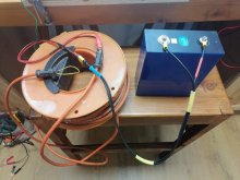
I used the household extension lead in the picture below with a brand new 280ah LifePO4 cell.

I used an old 14 gauge 50ft cord with a simple loopback (yellow wire below) making the wire 100ft long.
I connected to the lead Live/Neg prongs with alligator clips using some existing cables from my garage.
You could connect the wires many different ways, just ensure the connections are solid.

The total wire resistance when tested, measured 2 ohms, 1 - 10 ohms is the sweetspot.

There were no sparks, nothing eventful connecting the wires.
No wires got hot, not even slightly warm
I checked the voltage every minute with a multimeter

The voltage dropped from 3.6v to 3.3v in 15 minutes

All in all, a success. I would recommend this method.
61480AF8-A7B4-4CC5-BABA-6849BEE6AF89.jpeg
 
Last edited:
While I like your idea reusing your existing materials, most people won't have this type of cable laying around.

The voltage drop from 3.6 (directly after charge) to 3.3 is something that would happen naturally after disconnect the charger.
(But will take hours/days to stop at 3.375)

The numbers are to rough* to really say how much you discharging, and what's the C rating of the discharge.

* 3.6 to 3.3 is about 30% charge drop.
It your meter is slightly off, 3.263, it's already about 50%...
= C2 discharge?


Essentially you are making a coil to charge with electricity.
This will create an EMF.

I do like the idea of re-using.

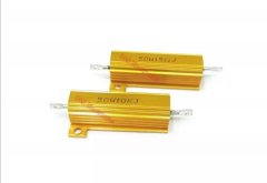
Personally I would use a 50 watt resistor.Screenshot_20210128_103758.jpg
It will provide more control over the discharge and a lot easier to move around :)

Still...
If you don't have this type of resistor, yours is a perfect way of discharging!
 
Last edited:
Thanks for the feedback, I have that exact resistor and it gets really hot after a few seconds on a 280ah cell and had to be disconnected, That's why i changed to using the extension lead.

The extension lead is a pretty common item in most house holds i think?

my 280ah cell had been at 3.6v for months when i discharged it, on lifepo4 cells, that's right at the end of the charge and doesn't represent much actual power, just a few percent, not 30%..

the resistors works well for small cells. though...
 
The capacity of the cell is irrelevant for the discharge.

50 watts is indeed hot, but supposed to get hot.
That's what it does, burn of by heat :)
0.3 ohms should give about 45 watts.

Lower 0.2 is 65 watts and can't be used long on 3.7v (as the rating is 50 Watts)

Extension cord is indeed common to have, yours seem really thick for 2.5mm2 (14AWG)
Thick insulation makes it better resistant to heat :)

A full short with 30 meters 2.5mm2 / 14AWG wire :) I'm sure it works.

Cell voltage after charge usually drops to 3.375v.

You are the first person I hear that their cell stayed at 3.6v!
That must be really high quality cell.

My Eve 280's and 152's drop quickly after reaching the 3.6 and charge is stopped.

From what I read, most people cells settle down to 3.375v after reaching 3.65v charge, and being kept there to assure full charge.

Rounding up numbers on LiFePO4 on 1 digit is for me too rough.
3.2 and 3.3 is roughly 50% difference in SOC.

I need to add that SOC and voltages are really bad indicators on LiFePO4.
Especially in the 3.20 to 3.35v range.
Even accurate voltage readings on 4 digits just give indication.

Using one digit (3.3), it's not uncommon to be 30 to 50% wrong.

Again, I do appreciate you sharing, and it's a good solution to bring a cell down quickly.

2 ohms at 3.7v
1.85 ampere.
About 7 watts.

In 15 minutes you discharged the cell 1.85 :4 = 0.5 ah.

If the cell was 100% charged, you discharged it to 99.8%
That voltage should be over 3.45
(Where the standard numbers are:

100% 3.650
99.5% 3.450
99% 3.375
96% 3.363
90% 3.350v
--
70% 3.300v
(What gives the 30% discharge)


List goes on, I don't like to type it all on my mobile phone ?

It sure is a good way to discharge, at rate of 1.85A per hour.(and reducing with lower voltages)

If yours did 3.6 to 3.3 in 15 minutes, some measurements are off.

That's OK.
I'm not fighting your solution, I think it's a good one.

People should measure the resistance first, and can calculate how quickly it will discharge.

Discharge a cell in rest (no charge or discharge for days) from 3.6 to 3.3, (where it after disconnect still stays 3.3v) with total 0.5ah in 15 minutes, that cannot be correct.

If it was 3.6 in rest, it should be a few hours after the discharge back to over 3.450 (99.5%)
A 100Ah cell would be at 3.450.
280Ah cell should be higher.

Then again..
Voltages and SOC... It's almost the worse indicator possible, but all we have that easy accessable.
 
Essentially you are making a coil to charge with electricity.
This will create an EMF.

Nop, you effectively have two coils with current going in opposite directions so the magnetic field is mostly cancelled.

Even without that the inductance would be very low (low number of turn, air core, ...) so not a problem at all ;)
 
I used an old 14 gauge 50ft cord with a simple loopback (yellow wire below) making the wire 100ft long.

The total wire resistance when tested, measured 2 ohms, 1 - 10 ohms is the sweetspot.

14 awg is 2.53Ω per 1000 ft.
2.53/1000 x 100 = 0.253 ohms.
3.5V/2.53 ohms = 13.8A
3.5V^2/2.53 ohms = 48W

Are you sure its really 14 awg, not 20 awg with counterfeit UL label?


"Investigation by CSA International has revealed that the cord’s conductor size is not 16AWG as printed, but is actually 26AWG."
 
Seen from the results @BarkingSpider is seeing, mathematical it can't be awg14, the internal resistance is too low.
If it's awg20, that absolutely makes a lot more sense!

It is a nice solution that many people can use if they don't have a special ceramic discharge resistor available!!
 
I suggest a longer cord so it is run well below its ampacity. Or else unroll the cord from the reel for cooling.
I ran near ampacity rating on UF that was coiled and it melted the inner layers of cable. Then it tripped the breaker. Which you don't have.
 
:)
I've done that also one time.
But that was with AC and over half the rating for longer periods of time with peaks towards the max rating.

In this setup, way under 100 watts loads.. I doubt it will be an issue.

For normal use of extension cord, absolutely unroll them when you are planning on powering anything above 500 watts.
(For 3000 watt rated cord)
 
I came up with 14A in a 14 awg extension cord (20A ampacity but 15A max per NEC if 90 degree C).
So right at full load for uncoiled, or even over rating for this type. As if driving a 1680W load with 120V. Given enough time in a coil at 50W dissipated it would overheat.

If actually 20 awg, just as high a percentage of ampacity, but 1/8 the total power with same mass of plastic to heat so will last a while.
 
If you're really pressed for time I would use the more intelligent "selectively use a charger" strategy other people have described before ruining a perfectly good extension cord. Having said that resistance is resistance so if your multimeter can measure 2 ohms accurately then who cares what AWG it is; just go with the resistance measurement. An extension cord has a lot of area to dissipate heat.

If you want to buy a power resistor they're only a couple bucks plus shipping. In a former job I tested a high current DC/DC converter I put on a PCB design using some 50W resistors like this (they're available in various resistances; this is just the 1Ohm version).


The more legitimate way to test these things is a "load tester" which is a benchtop lab instrument costing a few hundred dollars. I'm assuming that's out of the question in this context.
 
:)

You aren't "ruining a perfectly good extension cord"
It stays in tact.

And where it not might be the most perfect solution, it's A solution that doesn't cost money (you already have it) and doesn't cost much time to adjust for this purpose.

Sure, many different options to lower the SOC.

When you don't have a resistor by hand to discharge, this is easy and available in most households :)
 
Thanks fhorst...

Please ignore all these horror stories and controversial theories about using an extension cord.

Your not using 120v or 240v AC, but 3.2v DC. Very different.

Take advice from someone that has actually used this method with a new 280ah cell.

"There were no sparks, nothing eventful connecting the wires. No wires got hot, not even slightly warm."
 
+1 for BarkingSpider’s method! I used it recently on a high 310 Ahr cell and it reduced the V from 3.6 down to 3.3 in about 15 minutes, no sparks, no warm wires, no muss nor fuss. My measured R of extension cord was 4 ohms.
 
Back
Top