diy solar

diy solar

Safe Grid Use of the 5000ES and transformer

This is a copy from post # 1, read the DISCLAIMER: No warranty of the purchaser's safety. Does this sound safe to you?

So in summary if you buy one and you cannot get it passed they are going to tell you your SOL. If you get electrocuted or the unit burns down your house while using their "SAFE" wiring your SOL.

Why does this thread title still say "Safe Grid Use" if Signature Solar is not willing to guarantee it's safe?
 
Yes I find it really strange that they say there is no Trace but did not provide a picture. I would think after all of this bad PR they would want to post a picture ASAP. At this point what I really want to see more than anything else is an existing owners board. Someone who had theirs before all of this came to light.

The fact that Growatt says there is no difference between the ES and US version makes me believe that the screw is removed when they arrive in the USA. Growatt sure as hell does not want a mix up to happen at their warehouse and a batch of units with missing grounds are sent to Europe. The EU does not play games when it comes to regulations, if something like that happened they would suspend all Growatt sales in the EU.
Since they did not change the sticker to show the unit as SPF-5000 US, the sticker and the user manual still show as SPF-5000 ES as we have seen some of the pictures of the units that the members here had purchased from SS , how do they keep track as to which is which. BTW, is the so called US version still has the AC in/out terminals labels still show L, N, and Ground, or is it updated? If not the original installer some has to work on it and look at the spec sheet and user manuals it will be confusing.
 
Last edited:
1642534857790.png

This is a copy from post # 1, read the DISCLAIMER: No warranty of the purchaser's safety. Does this sound safe to you?
They also need to put the notes that the two Grounds must be bonded together.
 
So in summary if you buy one and you cannot get it passed they are going to tell you your SOL. If you get electrocuted or the unit burns down your house while using their "SAFE" wiring your SOL.

Why does this thread title still say "Safe Grid Use" if Signature Solar is not willing to guarantee it's safe?

I think that is "once again" not "still"

Thought for a time it was renamed per my suggestion:


But now it is "Updated"

 
I think that is "once again" not "still"

Thought for a time it was renamed per my suggestion:


But now it is "Updated"

Yes I remember the change of name (Safe?) which was changed again purely for the optics.
 
1642534857790.png

This is a copy from post # 1, read the DISCLAIMER: No warranty of the purchaser's safety. Does this sound safe to you?
The Diagram provided by Signature Solar/Growatt is not representative of typical US 240/120 Split Phase utility service. The Neutral from the Utility Meter to the Main panel is missing in this diagram. That is NOT how US split phase power is supplied from the utility companies.

In the US the main panel is split phase with a Neutral from utility transformer. Because the Growatt does NOT pass Neutral from Main to Load panel, there is a Neutral to Ground bond in both main and load panels. In this configuration there will be issues with Recirculating Current thru the ground wire due to the Autotransformer balancing ALL loads between it and utility transformer if the inverters are ever in AC Pass Thru. That ground wire might be carrying a LOT of current in this scenario. Ground wires shouldn't carry any current. The Autotransformer could be easily overloaded also.
 
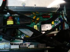
One seller studied the issue and is pulling the plug and recalling the units. Here is their video, audio sucks but around 19 min mark he shows the board and the issue with just removing the screw. There is another larger board under the top board and yes, the top board can easily contact the lower board with the screw removed.
 
Still waiting on pictures of this area of the circuit board, both sides.
But what I know ATM is on 2 different units I have access too, there is a wire link designated on the board that the manufacturer populates or not depending on the application.
ONLY removing/omitting this wire link position provides the necessary safe isolation as determined by the manufacturer.
Again they do this because it is electrically necessary, not because they wanted to cost themselves extra time and money doing extra work.
The reason Solar Power CA is recalling the units is due to the fact with their testing, the unit would still be able to make a connection to ground with the screw removed. It's in the video.
 
The Diagram provided by Signature Solar/Growatt is not representative of typical US 240/120 Split Phase utility service. The Neutral from the Utility Meter to the Main panel is missing in this diagram. That is NOT how US split phase power is supplied from the utility companies.

In the US the main panel is split phase with a Neutral from utility transformer. Because the Growatt does NOT pass Neutral from Main to Load panel, there is a Neutral to Ground bond in both main and load panels. In this configuration there will be issues with Recirculating Current thru the ground wire due to the Autotransformer balancing ALL loads between it and utility transformer if the inverters are ever in AC Pass Thru. That ground wire might be carrying a LOT of current in this scenario. Ground wires shouldn't carry any current. The Autotransformer could be easily overloaded also.

I think their diagram may show an "AC in panel" that is dedicated to the inverters, and isn't a "Main panel"?
At least I assumed that because it lacks a main breaker, which needs to be between utility meter and branch circuits.

One seller studied the issue and is pulling the plug and recalling the units. Here is their video, audio sucks but around 19 min mark he shows the board and the issue with just removing the screw. There is another larger board under the top board and yes, the top board can easily contact the lower board with the screw removed.
The reason Solar Power CA is recalling the units is due to the fact with their testing, the unit would still be able to make a connection to ground with the screw removed. It's in the video.

See? We "armchairs" who only looked at a schematic and read text, didn't have any skin in the game in the form of a GroWatt in our possession, didn't know what we were talking about :ROFLMAO:

That some of us can visualize the PCB trace, case, and screw, have designed PCB or otherwise observed traces/vias/annular rings meant we could foresee slight displacement of PCB (pressure from probe tip shown in video) makes contact. No where near the multiple mm of clearance required by standards.

If there is a GroWatt unit with PCB modified (or standoff removed) so proper clearance, then it can be OK.

Transformers so AC in and AC out are 230V line/neutral (rather than split phase with two hots) would make it usable.
 
The fact that you and several others have requested this over a week ago, and they have been testing for several days and did not show pics of the board as soon as they got in there leads me to assume we will not like what we see.

One seller studied the issue and is pulling the plug and recalling the units. Here is their video, audio sucks but around 19 min mark he shows the board and the issue with just removing the screw. There is another larger board under the top board and yes, the top board can easily contact the lower board with the screw removed.

Props to "Solar Power Storage" for pre-emptively shutting down sales and recalling in the name of SAFETY.

How does this solar company give us an update with video before SS when they have been in that unit over a week? They are absolutely hiding this. If SS is going to make the claim "The PCB is not the same" on their units they need to physically show me.
 
Last edited:
I have these units, and have installed these units from SS. Nice unit, works great, no issues. These were received last year, 2021, in Nov.
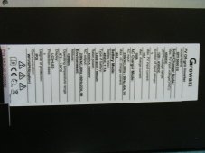
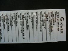
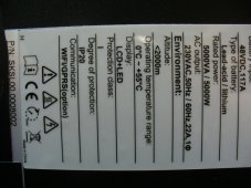
Yes, the Labeling is incorrect on the Nameplate and the N labeled connections, but SS clearly states that N is L when purchasing. Yes, the labeling does need to be changed, as, everyone is confused and there is no way to tell the difference between a ES and US unit, as they are are labeled ES.
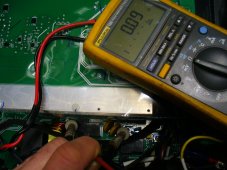
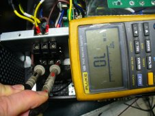
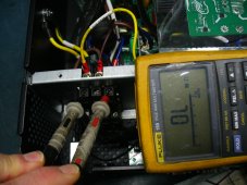
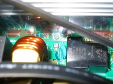
Attached are pictures of the unit showing the N and G are not tied. Pictures also show the PCB has been modified as SS claims, as the ground screw people remove on other sellers units is still in place and grounded. This means that the Neutral trace has been changed to floating line on the PCB(I haven't looked any farther at this point, just wanted to put this put there to satisfy curious minds)
 

Attachments

  • growatt spf5000es13.JPG
    growatt spf5000es13.JPG
    574 KB · Views: 71
  • growatt spf5000es10.JPG
    growatt spf5000es10.JPG
    585.4 KB · Views: 57
  • growatt spf5000es9.JPG
    growatt spf5000es9.JPG
    582.3 KB · Views: 56
  • growatt spf5000es6.JPG
    growatt spf5000es6.JPG
    597.1 KB · Views: 54
  • growatt spf5000es7.JPG
    growatt spf5000es7.JPG
    595 KB · Views: 50
  • growatt spf5000es8.JPG
    growatt spf5000es8.JPG
    612.7 KB · Views: 62
  • growatt spf5000es4.JPG
    growatt spf5000es4.JPG
    533.3 KB · Views: 69
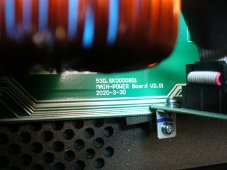
Attached are pictures of the Main Power PCB in question.
 

Attachments

  • Growatt PCB2.JPG
    Growatt PCB2.JPG
    600.2 KB · Views: 52
  • Growatt PCB5.JPG
    Growatt PCB5.JPG
    605.5 KB · Views: 52
Attached are pictures of the Main Power PCB in question.

I think this inverter (or the ES) used a relay to bond Neutral to Ground only when not fed by grid.
Unfortunate when they isolated the net, they didn't pull that relay connection out to a terminal. If they had, it could have served to ground center-tap of autotransformer (instead of grounding what they call "N" and the US model uses for "L2".

I think the Victron inverter/autotransformer sends a signal from inverter to autotransformer to control its ground relay (and suppresses relay inside inverter, which would have grounded one leg.)
I might be mis-understanding this, but when mine is on battery (no grid input at all), N/G are not bonded
 
I might be mis-understanding this, but when mine is on battery (no grid input at all), N/G are not bonded

If your 120VAC does not have neutral bonded to ground, that isn't correct for US market. In a house, RV, or boat, it should be grounded.
A floating neutral would become a hot neutral if line finds a path to ground. That would electrify chassis of some equipment, the (poorly shielded) outer terminal of a light socket. Most devices only switch off line, not neutral.

Check voltages between all pins of a 3-prong outlet. If safe/feasible, check for neutral bonding. One way I might try is with a light bulb between line and ground, see if it lights and again check all voltages between wires.
I bond them in the panel

Well to be more clear I use mine to plug into an interlock switch gated plug. They are unbonded at the hot-side of the plug, but the panel itself bonds them. I use mine to "simulate" a generator backup with the N/G *not* bonded.
 
Just so long as there is always a N/G bond for your loads, but not two bonds (one at utility entrance and one downstream) such that ground conductor carries neutral currents. Strictly on grid or off grid a screw probably does the job. It is switching power source that may require other approach. My system is grid-backup and neutral/ground continuity is maintained to utility entrance, so no need to switch anything.

Mobile units that sometimes plug into shore power require switching. It appeared the ES had a relay for that purpose. Not sure, but I think relay remains in the US model but a net is disconnected from it.
 
The fact that you and several others have requested this over a week ago, and they have been testing for several days and did not show pics of the board as soon as they got in there leads me to assume we will not like what we see.
I think you will! We have been testing a lot of things and trying to get as much content together to post as possible. Needless to say it's been a busy week, and we've been hard at work to make the community happy and safe.
 
I might be mis-understanding this, but when mine is on battery (no grid input at all), N/G are not bonded
It is bonded thru the inverter, the video shows this at the 20:30 mark. As this is a 240V European type transformer, there will be a bond at N-G.

Also, as Mike Holt indicates in his videos, electricity will return to the source which is the inverter. If you do not have N-G bond at the inverter, the G from you main panel to the inverter could potentially carry current.
 
Back
Top