diy solar

diy solar

Safety hazard w/ Growatt 5000ES (European version) when connected to American grid

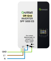
Here is a diagram of the system we had set up and showed in our Youtube video.

I still want to see all grounds bonded together with copper wire. Not two separate ground networks.

The output is not separately derived. When on-grid, L1 and L2 reach through to your inverters, loads, etc. so requires ground back to service entrance, and I think neutral back to service entrance as well.

I say this design will actively drive the two ground rods to different voltages when on grid and loaded unevenly between the two phases.
Earthworms frantically wriggle to the surface.
I agree with everthing EXECPT “seperately derived systems“ ...If part of the building is powered by the POCO and another part of the system is powered by an inverter this is a “separately derived system” , some of the power comes from the POCO and some of the power comes from the inverter. Hybird systems muddle this but they still are separate power sources.

I added the 480 volt service to my shop for the former owner/tenant but I was guided by my inspector to remove the ground rod from the 240 volt system and relocate it to the 480 volt ground buss.

And , yes the neutrals of all the systems must be connected as well as the grounds, back to the highest power panel.
I have 350 MCM between the neutral of my 240 volt panel and the neutral of the 480 volt panel. even though my 240 volt panel is used far more than the 480 volt service.

That is true even if In the case of my generator that has its own power panel that cannot transfer power either way to or from to the 240 volt panel, my inspector required the neutral and ground to be connected.


That is exactly how we did things at GE, we were exempt from the county building code but not from OSHA so we toed the NEC to the letter. OSHA carries a very big bat in industry....
 
Last edited:
Another little tidbit in the code, When using several different power systems the neutral and ground “MUST BE” connected at one place and one place only , that required that the neutrals of both systems to be connected and the neutral ground bond for the 240 volt panel was done in the 480 volt main panel....I had to install a floating neutral buss in my 240 volt panel to meet that provision of the code.
 
It has to. It's designed for European grid. Sounds like you have a defective unit.
I am from Netherlands and studied this subject. As I read on April 2022 on page 12 of the GroWatt SPF 5000 ES manual I have to use the 'Dry Switch' to make the connection between the GND and N when using the inverter in Battery mode. I think they modified the units and there is no standard connection between GND and N in the European versions anymore.
Manual URL: https://www.stralendgroen.nl/wp-content/uploads/2021/05/User-Manual_Growatt-SPF5000-ES_2020_ENG.pdf
 

Attachments

  • Use DRY-switch to connect N to GND.png
    Use DRY-switch to connect N to GND.png
    309.2 KB · Views: 19
  • User-Manual_Growatt-SPF5000-ES_2020_ENG.pdf
    4 MB · Views: 5
I am from Netherlands and studied this subject. As I read on April 2022 on page 12 of the GroWatt SPF 5000 ES manual I have to use the 'Dry Switch' to make the connection between the GND and N when using the inverter in Battery mode. I think they modified the units and there is no standard connection between GND and N in the European versions anymore.
Manual URL: https://www.stralendgroen.nl/wp-content/uploads/2021/05/User-Manual_Growatt-SPF5000-ES_2020_ENG.pdf
I'm not sure the Dry Switch is rated to handle the currents/voltage; in the manual you link to on page 19 program 24 contains the words
"""
This function is only available when the inverter is working with external grounding box. Only when the inverter is working in battery mode, it will trigger grounding box to connect neutral and grounding of AC output.
"""
which rather suggests the grounding box is required to perform the connecting.

I've imported 3 Growatt SPF 5000ES from China to the UK, and they come with the version 4.0 manual which does not mention program 24 (see https://autosolar.es/pdf/SPF 3500-5000 ES User Manual.pdf). The Dry Contact signal is now described as
"""
There is one dry contact(3A/250VAC) available on the rear panel. It could be used to deliver signal to external device when battery voltage reaches warning level.
"""

I wish to use a pair of these inverters; as far as I can tell there will be a neutral-to-earth connection in each of the inverters on the AC-out side. I guess this will be OK as long as AC-out RCB (100A 230V) is positioned after both AC-out have been connected together.
 
Last edited:
I'm not sure the Dry Switch is rated to handle the currents/voltage; in the manual you link to on page 19 program 24 contains the words
"""
This function is only available when the inverter is working with external grounding box. Only when the inverter is working in battery mode, it will trigger grounding box to connect neutral and grounding of AC output.
"""
which rather suggests the grounding box is required to perform the connecting.

I've imported 3 Growatt SPF 5000ES from China to the UK, and they come with the version 4.0 manual which does not mention program 24 (see https://autosolar.es/pdf/SPF 3500-5000 ES User Manual.pdf). The Dry Contact signal is now described as
"""
There is one dry contact(3A/250VAC) available on the rear panel. It could be used to deliver signal to external device when battery voltage reaches warning level.
"""

I wish to use a pair of these inverters; as far as I can tell there will be a neutral-to-earth connection in each of the inverters on the AC-out side. I guess this will be OK as long as AC-out RCB (100A 230V) is positioned after both AC-out have been connected together.
Having made the above reply, I measured the output GND to N resistance and it came out at infinite Ohms. Interestingly the input GND to output GND resistance was about 40 milliohms. Unless something happens when power is applied (e.g. relay) the statement "I think they modified the units and there is no standard connection between GND and N in the European versions anymore." looks to be true for at least one of my Growatt SPF 5000 ES inverters.
 

Attachments

  • IMG_1613 (1).jpeg
    IMG_1613 (1).jpeg
    129.8 KB · Views: 13
Just talked to signature solar and their 5000ES has the ground neutral bond removed in every unit. This must be what you're referring to @Struc
Interesting. I wonder when they started removing the screw. I purchased two 5000ES units from @SignatureSolarJames September, 2021, and they have the grounding screw in them. Perhaps it was a manufacturer error on the ones I received, because in a SS video James clearly states that they ordered the "right" units without the bonding screw.

My 5000ES also has three screws marked as ground, so my question is: Do I remove only the screw circled with pink below, or also the two marked in red?

I will be using the inverter in SBU mode, and DO plan to use the inverter with AC input (AC bypass) mode occasionally when my solar and battery cannot keep up with my loads. My neutral and ground are bonded at my meter panel on a pole outside.
 

Attachments

  • growatt-5000es-bonding-screw.jpg
    growatt-5000es-bonding-screw.jpg
    189 KB · Views: 19
Last edited:
What I don't understand is, why would these inverters blow up when the output is shorted ?

It should be designed to turn itself off if that happens.

boB
 
Interesting. I wonder when they started removing the screw. I purchased two 5000ES units from @SignatureSolarJames September, 2021, and they have the grounding screw in them. Perhaps it was a manufacturer error on the ones I received, because in a SS video James clearly states that they ordered the "right" units without the bonding screw.

My 5000ES also has three screws marked as ground, so my question is: Do I remove only the screw circled with pink below, or also the two marked in red?

I will be using the inverter in SBU mode, and DO plan to use the inverter with AC input (AC bypass) mode occasionally when my solar and battery cannot keep up with my loads. My neutral and ground are bonded at my meter panel on a pole outside.
The "removed the screw" is a misunderstanding of what Signature Solar actually did. They went to Growatt and had them build a US version of the product. A 'Relay' was changed (along with the circuit board) that no longer bonds the 'N' (L2 in the US) to ground. You will find the 'Screw' is still in the unit it just no longer has a 'live' electrical connection. You have to check for bonding by testing for continuity between the 'N' and the 'G' terminals when the unit is running on Grid Power.

My units were purchased over a year ago as well and that is how they are wired up
 
I don’t understand this

No European invertor should have a constant neutral ground bond it’s manifestly against European code when the invertor is not active. Even if active of its grid tied there should not be a neutral ground bond.

It’s only on non grid tied mode while the invertor is active shoujd the neutral and ground ( PE) be bonded

Victron does this with a neutral ground bonding relay that’s trips in when the invertor is powered ( non grid tied )

There should only be one active common bonding connection in a system. In a house that’s the incoming Neutral bond to ground at the meter box typically.

If this invertor is European it’s not passing CE regs if it has such a neutral permanent connection
 
Last edited:
I don’t understand this

No European invertor should have a constant neutral ground bond it’s manifestly against European code when the invertor is not active. Even if active of its grid tied there should not be a neutral ground bond.

It’s only on non grid tied mode while the invertor is active shoujd the neutral and ground ( PE) be bonded

Victron does this with a neutral ground bonding relay that’s trips in when the invertor is powered ( non grid tied )

There should only be one active common bonding connection in a system. In a house that’s the incoming Neutral bond to ground at the meter box typically.

If this invertor is European it’s not passing CE regs if it has such a neutral permanent connection

It has a PE-N relay as all Voltronic inverters like MPP Solar.
So when battery mode then it connects N_out to PE.
When line mode it connects N_in to N_out.
 
Then what is will P on about the invertor is quite safe

Lets start by looking at an EU inverter

1666905837335.png

Notice that the 240V output has a hot and a neutral that is tied to the ground wire and the inverter case when in invert mode.

In comparison, the standard US 240 V has two hots with a center tap neutral that is tied to ground.

1666906007442.png

This by itself is not necessarily unsafe, but anyone working on the system needs to understand what is going on.

Now let's hook up the AC-in to a North American 220.

1666906380209.png

Now it starts getting kinda weird. Notice that when in invert mode, one of the current conducting legs is a grounded conductor (Neutral) but when in pass-through, it is a hot wire, not a neutral. Depending on what loads are on the inverter, this might work OK, but now the person working on the system *really* needs to understand what is going on.

Now let's hook up an autotransformer so we can get split-phase from the inverter.

1666906933269.png
BOOM!!!! one leg of the autotransformer is shorted out through the bonding relay in the inverter.

OK..... let's switch it to an isolation transformer.

1666907129618.png

I * think* this works but anyone that is working on it better understand that the 240V output of the transformer switches back and forth between the US and EU standards. (I typically design and/or build the systems for someone other than myself and the opportunity for confusion by someone else is far to great for me to do anything like shown above.

If you are willing to let the circuit between the inverter and the isolation transformer float when in invert mode, you can improve on this by removing the Bonding-Enable screw in the inverter..... But I still would not do this.

1666907584098.png
 
This is not how a Euro inverter should work

Under any conditions where line voltage is present , the bonding relay should never be closed , hence only in pure standalone non pass through should the relay be closed.

In fact the whole idea of bonding relays in inverters is controversial, and some country codes don’t allow it at all.

In the situation where a auto transformer is being used to convert to split phase ( which is madness as you already have 230 vac generated ) the ouput of the auto transformer should be regarded as the inverter final point and the neutral bonded on on standalone invert.

Pass through to the auto transformer makes no sense , pass through should bypass the auto transformer


Given you’ve generated 230 vac there’s zero point in subsequently producing split phase , run your us 240. Ac from the 240 inverter.

Otherwise float the invertor and ground the auto transformer , this method has no consequence and is not unsafe, if yiu realky want braces and belts put a RCD trip device into the inverter to auto Traffo feed.
Creating multiple N, PE bonds is a bad idea anyway.

The whole thing is conceptually easy and safe. Regard the auto transformer as part of the invertor and treat it’s output as the generator output.
 
Last edited:
Proper way to use Euro inverter....Euro grid

Proper way to use a split phase inverter.........Split phase grid

Anything else is a hack

Want to do otherwise....it’s on your neck...not mine


I have several Chinese 230 volt inverters in my junkpile including a brand new 5kw power wall (The Fution...)
Removed from homes to clear Red Tag.......
While an auto transformer is a bit of a hack true. It’s perfectly safe and usable
 
Back
Top