diy solar

diy solar

Safety hazard w/ Growatt 5000ES (European version) when connected to American grid

Current will return to source but if a parallel path is provided, objectionable current will flow on a ground equal to 1/2 the total neutral current. It has nothing to do with "normal return is not available". If there is a parallel path, 1/2 the current will flow on each wire.
Return current follows the path of least resistance the current dividing as a proportion resistance of the path.

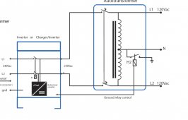
Have a look at the Victron circuit with the relay closed when the invertor is operating

375FCBA8-263A-4BF1-82B5-E47B40C816C3.jpeg
There is no PE current flowing in the auto transformer nor is there a neutral current except in the neutral of the auto transformer.

Trace the current path. There’s no path for the L1 L2 return currents via PE.

If your scranario was true it would not be possible to have a neutral ground reference 240 auto traffo. It’s obviously the case that you can.

I should add that where a neutral pe bond is already in place ie on pass through. It would not be recommended practice to bond the output neutral to PE as this creates ground loops. It’s only when the invertor is operating and the implicit assumption is the grid tied neutral PE is not in place in this case

Ie the golden rule is one PE neutral bond operative at any time. Which is why in thd Victron circuit the relay is present.
 
Last edited:
I’m sorry but I used many auto transformers and under normal non fault conditions current does not flow in the PE wire. If it did all my RCBOs would trip.

Yes, RCBO would trip if the circuit caused such ground current (30 mA for typical European whole-house protector, 5 mA for U.S. branch circuit.)

Do you have RCBO on a source that has neutral, is feeding an auto-transformer with center-tap grounded, and has unbalanced load?

If you really are concerned about this then a galvanically isolated split phase output put transformer can be easily sourced , ie 240 to 240 centre tap , this guarantees no current can possibly flow in the ground line, except under equipment failure conditions

Yes, that is what several of us have been telling people to do if they really want to use a 240V single-phase inverter between U.S. split-phase grid and loads.

Something is wrong here. Current returns to the source not via the neutral PE bond

Current returns to its source, follows a loop.

As shown in the schematic, source was +/-170Vpeak (120Vrms), midpoint grounded. That represents utility grid. In reality that is the secondary of utility transformer, and center tap neutral is grounded at my house. From there, neutral is wired to loads, and ground is wired to chassis of loads. The fact there is a ground rod has nothing to do with where current flows, because it is a single-point ground. (Same in the SPICE schematic, only one ground symbol so no current flows into it, but SPICE requires a DC path from all nodes to ground.)

Without auto-transformer, current from the utility source Line2 would flow through Rload and back through Neutral to the source. That's if you connected Neutral. If you instead connect ground to Rload, current flows back through ground.

With auto-transformer, there are two ways for current exiting Rload to get back to source. From what you say, your derived_neutral from auto-transformer (where load is connected) has a ground wire back to utility, and that ground wire is bonded to utility neutral. That is one resistive path. A second path is through the auto-transformer to L1. Auto-transformer tries to have equal current flowing through windings connected to L1 and L2. But not in same direction! The currents flow in opposite directions. To have 7Apeak flow in resistive load, 3.5Apeak flows from L1 through winding then through derived neutral and into Rload. Another 3.5A peak flows from L2 (in the opposite direction voltage of L2 wants to push current) through L2 and adds another 3.5A in derived neutral (for a total of 7A in derived neutral) and through Rload. L1 and L2 each supply 3.5A from utility, but 7A flows in Rload.

That's if there is no other way for current to get back from derived_neutral to utility neutral. But you've connected ground wire (which will happily carry 100% of current.) Current splits according to impedance. In my SPICE deck, about half went through ground wire and half through center-tap of transformer. On the bench, with a small auto-transformer having higher resistance skinny wires, 90% went through ground and 10% through auto-transformer center tap.

Current will return to source but if a parallel path is provided, objectionable current will flow on a ground equal to 1/2 the total neutral current. It has nothing to do with "normal return is not available". If there is a parallel path, 1/2 the current will flow on each wire.

Half the current if both wires of same impedance. If your Romex has 12 awg neutral and 12 awg ground, it would be about half.

With my auto-transformer, the house wiring had much lower resistance back to utility than the winding resistance, because the transformer was only a few hundred VA. With L1, L2, Ground wires from grid, 122V reached load, but with L1, L2, and only auto-transformer to create a derived neutral, 117V reached load. That was 5Vrms drop with 7A peak (5A rms) so something like 1 ohm in windings.

We’re you using a auto transformer or sn isolating transformer.

My bench test and the SPICE schematic I showed are equivalent, except the transformer on the bench was smaller.
It had a number of windings, and I connected identical windings in series to have a center-tapped auto-transformer.
(I left one winding isolated, and capped a number of un-used taps.)

Every isolation transformer with split-phase output will also act as an auto-transformer; when you backfeed utility with 240V from GT PV, if you (or neighbors sharing secondary) have a 120V load, the utility transformer's secondary windings derive a neutral and carry the power. Usually that doesn't cause an issue, but I've figured out the "120% rule" for GT PV breakers provides some protection against overloading that neutral.


I did an experiment. Now you do one. With only loads you can risk subjecting to incorrect voltage applied ...
With an imbalanced load (like my oil-filled radiator on one phase)

1) Measure current through center tap, and current through ground wire back to utility.
2) Disconnect auto-transformer and measure voltage across load, also current through ground wire back to utility.

Do you have a "ground" wire bonded to neutral somewhere around utility connection, as shown in my schematic? Does that ground wire also connect to both center tap of auto-transformer and to neutral of loads? If so, do you agree that without auto-transformer, current has to flow in your ground wire?
 
Yes, RCBO would trip if the circuit caused such ground current (30 mA for typical European whole-house protector, 5 mA for U.S. branch circuit.)

Do you have RCBO on a source that has neutral, is feeding an auto-transformer with center-tap grounded, and has unbalanced load?


Yes, that is what several of us have been telling people to do if they really want to use a 240V single-phase inverter between U.S. split-phase grid and loads.


Current returns to its source, follows a loop.

As shown in the schematic, source was +/-170Vpeak (120Vrms), midpoint grounded. That represents utility grid. In reality that is the secondary of utility transformer, and center tap neutral is grounded at my house. From there, neutral is wired to loads, and ground is wired to chassis of loads. The fact there is a ground rod has nothing to do with where current flows, because it is a single-point ground. (Same in the SPICE schematic, only one ground symbol so no current flows into it, but SPICE requires a DC path from all nodes to ground.)

Without auto-transformer, current from the utility source Line2 would flow through Rload and back through Neutral to the source. That's if you connected Neutral. If you instead connect ground to Rload, current flows back through ground.

With auto-transformer, there are two ways for current exiting Rload to get back to source. From what you say, your derived_neutral from auto-transformer (where load is connected) has a ground wire back to utility, and that ground wire is bonded to utility neutral. That is one resistive path. A second path is through the auto-transformer to L1. Auto-transformer tries to have equal current flowing through windings connected to L1 and L2. But not in same direction! The currents flow in opposite directions. To have 7Apeak flow in resistive load, 3.5Apeak flows from L1 through winding then through derived neutral and into Rload. Another 3.5A peak flows from L2 (in the opposite direction voltage of L2 wants to push current) through L2 and adds another 3.5A in derived neutral (for a total of 7A in derived neutral) and through Rload. L1 and L2 each supply 3.5A from utility, but 7A flows in Rload.

That's if there is no other way for current to get back from derived_neutral to utility neutral. But you've connected ground wire (which will happily carry 100% of current.) Current splits according to impedance. In my SPICE deck, about half went through ground wire and half through center-tap of transformer. On the bench, with a small auto-transformer having higher resistance skinny wires, 90% went through ground and 10% through auto-transformer center tap.


Half the current if both wires of same impedance. If your Romex has 12 awg neutral and 12 awg ground, it would be about half.

With my auto-transformer, the house wiring had much lower resistance back to utility than the winding resistance, because the transformer was only a few hundred VA. With L1, L2, Ground wires from grid, 122V reached load, but with L1, L2, and only auto-transformer to create a derived neutral, 117V reached load. That was 5Vrms drop with 7A peak (5A rms) so something like 1 ohm in windings.


My bench test and the SPICE schematic I showed are equivalent, except the transformer on the bench was smaller.
It had a number of windings, and I connected identical windings in series to have a center-tapped auto-transformer.
(I left one winding isolated, and capped a number of un-used taps.)

Every isolation transformer with split-phase output will also act as an auto-transformer; when you backfeed utility with 240V from GT PV, if you (or neighbors sharing secondary) have a 120V load, the utility transformer's secondary windings derive a neutral and carry the power. Usually that doesn't cause an issue, but I've figured out the "120% rule" for GT PV breakers provides some protection against overloading that neutral.


I did an experiment. Now you do one. With only loads you can risk subjecting to incorrect voltage applied ...
With an imbalanced load (like my oil-filled radiator on one phase)

1) Measure current through center tap, and current through ground wire back to utility.
2) Disconnect auto-transformer and measure voltage across load, also current through ground wire back to utility.

Do you have a "ground" wire bonded to neutral somewhere around utility connection, as shown in my schematic? Does that ground wire also connect to both center tap of auto-transformer and to neutral of loads? If so, do you agree that without auto-transformer, current has to flow in your ground wire?
Do you feed your experiment with split phase. 240 vac

In my previous case , I had RCBO on each split phase ( in my case the system was single phase input , 110vac split phase output.

It should be pointed out that if your pe is already bonded , you no NOT then bond the auto traffo neutral. Ie one neutral pe bond should only exist.

In effect the auto trans transformer neutral is already PE referenced anyway in this situation
 
Yes, I plugged into an outlet with 120/240V split-phase, L1, L2, N, G

Cheater cord has shrouded Banana plugs Red, Black, Yellow, Green.
Auto-transformer has Red, Black Yellow.

What I did was feed auto-transformer 240V L1, L2 by connecting Red to Red, Black to Black.
Resistive load (white test leads) go to Black (L1) and the auto-transformer's Yellow (derived neutral).

First picture, Green (utility Ground) is not connected to anything (except socket; from there wired to main panel where Neutral and Ground bond together.)

Second and third pictures, Green (utility ground) is connected to auto-transformer's Yellow (center tap now grounded.)


You had said "Something in your spice model is wrong."
The SPICE model is what it is, and simulation matches my expectations. How current splits between ground and center tap depends on resistance (and coupled inductor properties.)

How does your application compare the the SPICE schematic? I meant it to represent how I understood yours to be connected.
Mark up if different, or add what's missing to the schematic you posted (which I tried to do.)

 
My point was that bonding the auto transformer neutral to PE is contrary to code if a pe neutral bond is already present. Hence the neutral has to then left floating. Ie only one pe neutral bond to avoid earth loops.

This of course has certain issues where the phases are grossly imbalanced

It’s only in non grid tied invert mode should the auto neutral be bonded to PE.

These problems are common in all split /multi phase systems.

Are you then saying people should connect:

120/240V split phase --> 240V single phase inverter --> auto transformer (isolated neutral) --> 120V and 240V loads?

But here you said "Grid Neutral PE Bonded", and you also connected auto-transformer neutral center tap back to PE.
I think that is a contradiction.


What do you have in your system? I've been trying to demonstrate by SPICE and bench test that it has "objectionable current" in ground, which you say it does not. But if you leave out the derived neutral to ground bond, I think I can show a shock hazard.

With a schematic of your system, I'll try to analyze it, and challenge you to go measure ground current (as I requested earlier.)

We (on the forum) hashed out the auto-transformer for GroWatt pretty thoroughly before you arrived.
It seemed to us that when fed from U.S. grid, which passes through the inverter, an auto-transformer couldn't be used without some problems (unless suitable switching implemented.) With switching, we were concerned about briefly apply 240V to 120V loads during the transition.
It appeared to us that an isolation transformer was the robust solution, and could be done without any NEC violation (other than if inverter was not UL listed), and without any shock hazard or "objectionable current" in ground.
 
  • Like
Reactions: Zwy
It appeared to us that an isolation transformer was the robust solution
Exactly, anything else was a hack that caused other issues unless done 100% right.
Problem was, 100% right meant you had spent more money on parts and time than you had saved buying a device that was not suitable.
DIY experiments and testing is great, I am doing it but please don't run your family day to day life with bodge up's.
 
Are you then saying people should connect:

120/240V split phase --> 240V single phase inverter --> auto transformer (isolated neutral) --> 120V and 240V loads?

But here you said "Grid Neutral PE Bonded", and you also connected auto-transformer neutral center tap back to PE.
I think that is a contradiction.


What do you have in your system? I've been trying to demonstrate by SPICE and bench test that it has "objectionable current" in ground, which you say it does not. But if you leave out the derived neutral to ground bond, I think I can show a shock hazard.

With a schematic of your system, I'll try to analyze it, and challenge you to go measure ground current (as I requested earlier.)

We (on the forum) hashed out the auto-transformer for GroWatt pretty thoroughly before you arrived.
It seemed to us that when fed from U.S. grid, which passes through the inverter, an auto-transformer couldn't be used without some problems (unless suitable switching implemented.) With switching, we were concerned about briefly apply 240V to 120V loads during the transition.
It appeared to us that an isolation transformer was the robust solution, and could be done without any NEC violation (other than if inverter was not UL listed), and without any shock hazard or "objectionable current" in ground.
There’s is no difference using it in a single phase 240 or a split phase 240. The issue with the European Growatt is the Inclusion of a default PE neutral bond which is wrong for split phase supplies equally as it wrong for certain European floating neutral countries.

Hence most codes for the reasons you demonstrate do not recommend multiple neutral PE bonds, so if the grid input bonding is in place the neutral of the auto transformer is not then also bonded. This is consistent with the victron diagram.

There’s no additional shock hazard is this sceanario

It’s only in full independent non grid inverter activity , that the bond should be made at the neutral of the AT. This is consistent with NEC code.
 
Current returns to its source. Current will only flow through the ground line if the normal return is not available and then only under fault conditions.

Original statement which is incorrect.

Return current follows the path of least resistance the current dividing as a proportion resistance of the path.

Only if there is a large mismatch for wire size or length, the current will be reduced with the circuit with more resistance. However there will be current which is the point of my response. For short runs with wire close to equal size, the current will be 1/2 of total current of the 120V load.

You can't be much of an EE if you do not understand this.
 
Are you then saying people should connect:

120/240V split phase --> 240V single phase inverter --> auto transformer (isolated neutral) --> 120V and 240V loads?

But here you said "Grid Neutral PE Bonded", and you also connected auto-transformer neutral center tap back to PE.
I think that is a contradiction.


What do you have in your system? I've been trying to demonstrate by SPICE and bench test that it has "objectionable current" in ground, which you say it does not. But if you leave out the derived neutral to ground bond, I think I can show a shock hazard.

Yes.
With a schematic of your system, I'll try to analyze it, and challenge you to go measure ground current (as I requested earlier.)

We (on the forum) hashed out the auto-transformer for GroWatt pretty thoroughly before you arrived.

Most certainly. It was pages and pages, quite lengthy. I was pretty up on the conversation, forgot many of what was discussed but the end result is the only proper solution to using a Euro 240V inverter was the use of a isolation transformer.

It seemed to us that when fed from U.S. grid, which passes through the inverter, an auto-transformer couldn't be used without some problems (unless suitable switching implemented.) With switching, we were concerned about briefly apply 240V to 120V loads during the transition.
It appeared to us that an isolation transformer was the robust solution, and could be done without any NEC violation (other than if inverter was not UL listed), and without any shock hazard or "objectionable current" in ground.
Not only that but you see posts like this one where he was lucky he didn't fry his appliances. https://diysolarforum.com/threads/s...-connected-to-american-grid.33975/post-632197
 
Yes.


Most certainly. It was pages and pages, quite lengthy. I was pretty up on the conversation, forgot many of what was discussed but the end result is the only proper solution to using a Euro 240V inverter was the use of a isolation transformer.

No because then in Europe we would have to use isolating transformers and we don’t.

The point is floating European 230vac is in essence the same as us 240 split phase. In fact some European countries generate such feeds as a split phase.
Not only that but you see posts like this one where he was lucky he didn't fry his appliances. https://diysolarforum.com/threads/s...-connected-to-american-grid.33975/post-632197
 
Last edited:
Original statement which is incorrect.


Only if there is a large mismatch for wire size or length, the current will be reduced with the circuit with more resistance. However there will be current which is the point of my response. For short runs with wire close to equal size, the current will be 1/2 of total current of the 120V load.

You can't be much of an EE if you do not understand this.
People , intellectually challenged usually loosing arguments, decend into ad hominem attacks in my experience.
I have repeatedly stated as per the Victron diagram , there isn’t a ground loop as there is no connection. Between AT transformer neutral and PE unless non grid connected.
 
Last edited:
Again folks will P video correctly identified the presence of the incorrect earth neutral bond in the 240VAC invertor. He’s right in highlighting this. This is a source of the problem.

Victron have published auto transformer circuits for split phase which are displayed in this thread. These transformer only have a single pe neutral bond when operating in non grid tied.

In grid tied the AT neutral is not tied to PE as this bond already exists at the grid entrance as per NEC code.

A floating neutral AT is safe , as long as it’s used within its specs.

What I mean is a floating neutral is safe as long as thd grid PE neutral bond is present. Clearly in isolation , ie non grid. Thd AT neutral must be pe bonded as per the Victron diagram. This is also similar to such bonding in single phase invertors.

Of course the appropriate protections should be added on a floating neutral system. Failing , where dramatic phase imbalance is expected , that a isolating split phase transformer is better deployed. Ie 240 to split output isolated thus can be a common. 240 vac to 2x120 transformer of appropriate secondary ratings.

The AT imbalance issue should not be mixed up with the invertor bonding issue
 
Last edited:
Not even close, sorry.
Explain the difference then if you’re so sure you’re clearly familiar with the diverse range of European mains supplies you might want to include the very common 3 phase supplies as standard supplied domestically in many countries

Clearly you can further explain PME, TT TT-C-S and TT-N-S grounding strategies.

The US distribution network is similar as are all grid distribution strategies.there’s nothing unique about it. Every building sites here is utterly familiar with 110 vac and split phase as all electrical construction tools must be 110.
 
Last edited:
What do you think is up on that pole or inside those enclosures at the end of the street ???
Yep big ole isolating transformers, changing 11kv to 240v
But that’s the same every where whether it’s single split or multi phase domestic supply
 
Not even close, sorry.
Closer then you understand.

I’ll kick it off for you explain the difference between European 230 vac where it’s supplied as L1 L2 and US split phase supplying 240 vac.

Compare a different contrast this with rural French distribution with 3 phase to houses and also similar in Germany.

Many French rural farms are actually in practice split phase except the term split phase isn’t used.
 
Last edited:
Again folks bear in mind thd issue as Will P pointed out is the default existence of a neutral PE bond in the Growatt inverter this is the issue he correctly flags up.
 
Explain the difference then if you’re so sure you’re clearly familiar with the diverse range of European mains supplies you might want to include the very common 3 phase supplies as standard supplied domestically in many countries

Clearly you can further explain PME, TT TT-C-S and TT-N-S grounding strategies.

The US distribution network is similar as are all grid distribution strategies.there’s nothing unique about it. Every building sites here is utterly familiar with 110 vac and split phase as all electrical construction tools must be 110.
I only know basic's about the UK and USA systems. USA confused the shit out of me when I arrived lol.

I don't even know what those letters mean without looking them up, and guess what ? I don't care to.

I never worked on building sites so I know nothing about them apart from what I read on the interwebs.
 
Back
Top