diy solar

diy solar

Safety hazard w/ Growatt 5000ES (European version) when connected to American grid

Fingers should stay out of the PCB during normal operation...
I am talking about testing without power applied and the unit is not connected to anything, it is just Ohm test, which people who knows how to perform resistance test should know that there will be no power applied to the device during test, period! You do know that, right?
 
We recommend grounding the inverter 100% - this is a separate issue regarding a neutral/ground bond that by default is done at the inverter on most European models of inverters - and specifically with the 5000ES by a screw found on the PCB. I'll update as I am informed of more information.
I'm not sure but will speak with my bench team tomorrow to find out more information.

Yes, case needs to be grounded.
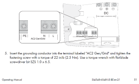
For my Sunny Island, there is a "PE" terminal on the PCB, that grounding conductor is fastened to.
The construction of the inverter takes care of connecting that net to enclosure. I don't have to run a separate wire to the enclosure.

The pictures posted here, I think of the GroWatt, have a grounding screw removed but I'm not clear from the board markings that is the neutral/ground bond, or the case/ground bond. Case grounding is normally tested for several 10 seconds with 10A AC, looking for < 0.1 ohms (or similar figures, I don't remember exactly). This would confirm a solid connection.

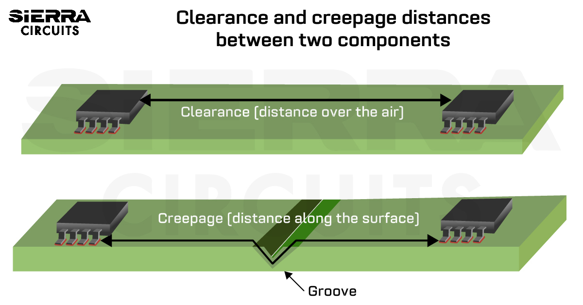
Isolating Neutral/Ground at the inverter is probably the thing to do when Neutral/Ground bond occurs at the utility entrance. And then very low voltage between them at he inverter, so not concerned about creepage/clearance. If "Neutral" becomes "Line2" in a split-phase configuration, then it has to withstand line voltage across it so those dimensions do matter.

1642479755895.png

Fingers should stay out of the PCB during normal operation...

Yes, when powered.
With all sources of power disconnected, a little experiment could check if isolation between "Neutral" (which is now repurposed as "Line2" and chassis can make contact. Ohm meter and pushing on PCB.

If you ship me one I'd be happy to try it out. And other things too. I'm a "Qualified Electrical Worker" :)
 
Yes, case needs to be grounded.
For my Sunny Island, there is a "PE" terminal on the PCB, that grounding conductor is fastened to.
The construction of the inverter takes care of connecting that net to enclosure. I don't have to run a separate wire to the enclosure.

The pictures posted here, I think of the GroWatt, have a grounding screw removed but I'm not clear from the board markings that is the neutral/ground bond, or the case/ground bond. Case grounding is normally tested for several 10 seconds with 10A AC, looking for < 0.1 ohms (or similar figures, I don't remember exactly). This would confirm a solid connection.

Isolating Neutral/Ground at the inverter is probably the thing to do when Neutral/Ground bond occurs at the utility entrance. And then very low voltage between them at he inverter, so not concerned about creepage/clearance. If "Neutral" becomes "Line2" in a split-phase configuration, then it has to withstand line voltage across it so those dimensions do matter.

View attachment 80175


Yes, when powered.
With all sources of power disconnected, a little experiment could check if isolation between "Neutral" (which is now repurposed as "Line2" and chassis can make contact. Ohm meter and pushing on PCB.

If you ship me one I'd be happy to try it out. And other things too. I'm a "Qualified Electrical Worker" :)
Got it. There is a seperate chassis ground for that specific purpose. I'll learn more if it's possible for the pcb to migrate to possibly touching the case. From what I have seen I doubt it but we definitely want to make sure. There are a lot of these models out there, both in the US and EU markets, and I've never heard of this happening under normal operations (or at all). At the end of the day these are just computers for electricity, and I know I have a huge GPU that hasn't sagged after 8 years of use....not to say it's not possible - just an observation of a similar situation.
 
Show me the schematic, and I'll show you the path for current to enter earth through dedicated ground rod and complete its circuit at utility service entrance ground rod.
Earthworms are going frantic!

I also think code requires the inverter chassis to be bonded to the ground of the electrical system feeding it.
 
Got it. There is a seperate chassis ground for that specific purpose. I'll learn more if it's possible for the pcb to migrate to possibly touching the case. From what I have seen I doubt it but we definitely want to make sure. There are a lot of these models out there, both in the US and EU markets, and I've never heard of this happening under normal operations (or at all). At the end of the day these are just computers for electricity, and I know I have a huge GPU that hasn't sagged after 8 years of use....not to say it's not possible - just an observation of a similar situation.
Well, the EU one has that ground installed for reason and not supposed to be removed, that is why no problem with EU unit using in the EU which the unit is designed for.
 
The following appears to show 1.5mm "creepage" across surface of FR4 PCB (material IIIa) in a fan-cooled box (pollution degree 2) for 125Vrms


Another set of distances may apply when "reinforced" insulation is required.
Double the distance, according to this link:


Those would apply if a 120V net and ground were near each other on the PCB.
If one is not on the PCB, separated by an airgap, then "clearance" distance would apply.

We're not clear if the screw is clamping copper of PCB to case (could make contact even with screw removed), or if screw makes connection from top side copper to case under PCB.
 
the chassis is using your dedicated ground mentioned earlier, the utility ground stays out of the system along with the utility neutral because they are the same thing.
This sounds arse backwards. In any industrial or home setup, the utility ground is a guaranteed fact.
 
So those that were already sold with just screw removed only and do not have insulation material installed? if not, then it just a matter of time that the PCB can make contact with the chassis due to vibration or loose PCB mounting screws or have arc over.
Just removing the screw is not enough. The link needs to be removed too. That will then give the proper clearance. There is a reason the circuit board is laid out this way.
 
The pictures posted here, I think of the GroWatt, have a grounding screw removed but I'm not clear from the board markings that is the neutral/ground bond, or the case/ground bond. Case grounding is normally tested for several 10 seconds with 10A AC, looking for < 0.1 ohms (or similar figures, I don't remember exactly). This would confirm a solid connection.
Just to be 100% crystal clear, the pictures I posted and refer to are a knock off unit from Vevor that has failed, not a Growatt or MPP unit.
However, as my knockoff and most others seem to be a copy of the MPP or Growatt, I suspect the circuitry could be similar in this area.
 
Last edited:
We would want to see pictures of the factory modification to GroWatt (because we're curious)

Such a change could be done, and submitted to an NRTL to obtain compliance for US market.
The NRTL ought to be checking creepage an clearance distances.
For human access to live parts, they apply a specified force to components. Hopefully could consider deflection possibility for "clearance".

Testing continuity would not be sufficient. HiPot testing would have a chance to jump a small gap and discover issues.
I'm not sure it would screen precisely for "clearance", but I've used one and noted with kV level was required to fire a spark plug.
That would ensure nothing short of a surge would arc across (unless dust buildup).
Proper grounding guarantees case don't become hot, and breaker trips if a bonded fault occurs.
 
The push on the PCB test is just a simple test to find out how much flexing of the PCB for the connection to be made, if I am correct, it will not take much movement for the PCB pad to make connection with the standoff, and BTW, if the standoff is actually removed then you should not be able to put the screw back in which is an easy test.
 
The push on the PCB test is just a simple test to find out how much flexing of the PCB for the connection to be made, if I am correct, it will not take much movement for the PCB pad to make connection with the standoff, and BTW, if the standoff is actually removed then you should not be able to put the screw back in which is an easy test.
I'll take a look at this hopefully today, it's been a crazy week as you can imagine. Will post when I get results.
 
Just a quick update, we are still generating additional schematics for different set ups (such as without the transfer switch) for everyone to utilize. As always, I welcome any feedback (publicly or through PM) on ways we can improve any aspect of your interaction with Signature Solar.
Glad you folks are sorting this out and are publicly engaging in active solutions. I have a Growatt 12kw 250 we acquired from u back last Nov. Multiple personal situations have stalled the install, but hope to have it installed by spring. Your efforts here are inspiring confidence in support if we need it along the way.
 
Glad you folks are sorting this out and are publicly engaging in active solutions. I have a Growatt 12kw 250 we acquired from u back last Nov. Multiple personal situations have stalled the install, but hope to have it installed by spring. Your efforts here are inspiring confidence in support if we need it along the way.
Glad to hear! (y)
 
So many of us jumped into off grid solar after watching hours and hours of video. My wife endured six months of listening to them. Real answers are so difficult to find. Finally after months, I called Signature Solar. Most times just left a voice mail. I think David’s videos are what convinced me. Of course no one answers phones now. I want to say thanks to all who’ve responded to this thread. Special thanks to Will. Spoke with Ian this morning. Seriously thinking of duplicating Wills video. I will be selling three brand new Gowatts and two mid point transformers. I have 36 each 450 watt panels, fuses, everything ready- just need to make final tie ins. I really don’t want to do this again. Thoughts on LVX6048 versus LV6545. I also have 21kWh of lithium batteries. At 76, I’m almost too old for this. Thanks
Truer words have never been spoken, I am thinking I should have gone with the sol-Ark
 
Not all, but a lot of these problems exist with other inverters as well. I haven't seen a discussion around grounding where everyone agrees on much.

I think there is too much reliance on regulations without understanding the fundamentals. Regulations aren't physics, sometimes they aren't actually the best choice.

I really wish manufacturers were more open with their designs. Especially since there are already clones of pretty much everything.
 
Back
Top