diy solar

diy solar

Sailboat 24/12V CALB setup check please

DeNn

New Member
Joined
Feb 8, 2020
Messages
8
Dear,

I have made up my mind about the system I would like to install on my boat. It consists of the following components:

Cells: 8* CALB 100Ah
BMS: 123SmartBMS or ??? (Something with low temperature disconnect)
Main switch: 2*701
Charger/ inverter: Victron Multiplus 24/1200 (incl. VE.Bus Smart Dongle)
Alternator: 60A
DC-DC charge controller: Victron Orion 12/24-15
Battery monitor: Victron BMV-712
DC-DC converter: Victron 24/12-20
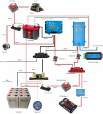
Electrical scheme 24V.jpg
At the moment I am not sure about using relays on the charge/ discharge on the batteries and which BMS to use.
I very much like the app from 123BMS but I am not the greatest fan of the PCB's that have to be mounted on the cells and the amp meters which can go faulty.

Furthermore, since I can still choose I am in doubt to change to a 24V system.

Would love to hear your comments.

Best regards, Dennis
 
Last edited:
Hi Dennis, welcome to the forum!

I'm impressed with your schematic. Looking good!!

CALB is a personal choice.
they have strong outside plastic, internal is "same same" prismatic cells as "all the others"

Yes, they are good quality, reliable reputation, but high priced.
A quick google search gave me price between $110 and $190 per cell, excluding transport.

You can have 280Ah for $ 79.80 - 82.67
Modern LiFePo4 Cells (any brand) are known to be reliable. They seldom go bad.
for that, it does not matter that much if you have CALB or other brand.
If you get the bad luck, getting the warranty is part 2.
If you buy at local shop who can and will do this for you... who provide you "no hassle warranty", then you can use it.
Sending defective cells to China as private person to claim warranty will cost you more money on transport, then buy a new one!!
(including the transport to your home)


The 123bms is interesting technology.
I like them, seen their video's and the idea of really on the cell manage that cell is good concept.
But not at those prices!! about $110 per cell !! (S4 kit is 380 euro, about $410 excluding transport)

Will talks about low temperature in this thread
and the Chargery thermal protection seems to work good.

moving up to 24v is "always" a good idea, it is less costly and uses less thick cables.
If you want to be more flexible for replacement inverter, 12v you can buy cheap all over the globe.
(if you are planning to take a trip around the globe)
Not the best quality and not always pure sine wave, but it will convert power.

I don't know the motor in your boat, a diesel could easy go up to 600CCA (cold cranking amps) that is during starting.
Your 150A might be on the low side.

Good luck!
 
Thanks for your reply Jhorst, much appreciated!

I am looking for the most reliable equipment,
therefore I came to the option of the 123SmartBMS (money is not the first priority, simplicity and functionality is. a gen2 123SmartBMS is available for 300 dollars, which still is a lot :) )

My preference for the 123SmartBMS comes from the additional functionality to connect to the charger/ inverter without the need to add additional relays.
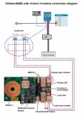
123Smart+Victron Combi.jpg

The engine is equipped with a 1.2kw starter, I assumed 150A would be on the safe side, would you recommend going to 250 maybe?

It seems like 24v is the way to go then!

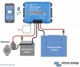
Another idea I have is splitting the risk of failure by installing a Victron Phoenix 24/1200 Inverter and install a Victron Blue Smart Charger, this being a little less sophisticated in charging but similar to the Orion Dc-Dc charger...
Saves me some money to upgrade to a bigger inverter as well...

Love to hear your thoughts,

Best regards,

Dennis
 
Last edited:
When your engine is running is the Orion controlling the charge to your starting battery? From your alternator.
 
I see. On my Rawson I had a 50amp alternator running to a much older type of charge controller which was charging my deep cycle house batt. It threw me off there.
 
The engine is equipped with a 1.2kw starter, I assumed 150A would be on the safe side, would you recommend going to 250 maybe?

The engine uses 12 volts, yes?
1.2kw starter motor is when running 100A
Electric motors have a high peak to start running.
(On its own)
And needing to crank an engine..
Makes it even more.

Normal motor start is 2 or 3 time higher then rated current.

Depending on the fuse (slow or normal)
(Slow fuse allow a few seconds high peak before flip /burn)

In case of real problem a 250, 500 or 750 amp all will flip / burn fast enough.

Price of a simple fuse is not that high.

For my battery array I use 300 AMP ANL Fuse Holder Distribution in line 0 4 8 GA Positive With ANL Fuse
Price 3.5 USD on AliExpress :)
500A is 4,5 USD.
 
CALB is a personal choice.
they have strong outside plastic, internal is "same same" prismatic cells as "all the others"

Yes, they are good quality, reliable reputation, but high priced.
A quick google search gave me price between $110 and $190 per cell, excluding transport.

You can have 280Ah for $ 79.80 - 82.67
Modern LiFePo4 Cells (any brand) are known to be reliable. They seldom go bad.
for that, it does not matter that much if you have CALB or other brand.

I don't entirely agree with what fhorst is saying here.

In the context of an off-grid house, or stationary system, he isn't wrong (in practice). But for marine and overland applications (as you may already be aware) structural integrity (external and internal) is much more important.

As fhorst noted, one of the main advantages of CALB (and Sinopoly, and Winston) is the robust plastic outer casing, but beyond just the outer casing the battery terminals are substantially more robust and I have heard (here and here) that with CALB the terminals are build into the casing, as opposed to spot welded as is the case with some or all of the aluminum blues.

Beyond this, for marine applications especially, an emerging best practice is using smaller cells ideally ~100ah cells but upto 200ah cells. The larger the cell the less internal structural integrity the cell has (internal volume increases at a greater rate than surface area) (see here)

Now, all that said, there are people that have safely used the aluminum cells for years without failure in harsh environments. And there are currently people building systems for overland and marine applications using aluminum cells. I'm sure it can be done safely. But from a pure structural standpoint smallish CALB cells seem like the way to go. On the other hand aluminum blues win in terms of price, weight, and size.

edit: I should note, everything I wrote above is based on my research, and the research of others, not firsthand testing, but I generally trust the sources of this information (Nordkyn Designs, Will, Dacian (electrodacus), forum members here).
 
Last edited:
Yes, from a pure structural standpoint smallish CALB cells seem like the way to go.

In harsh marine environment it's all about safety.
In the middle of the Pacific Ocean....
Compared to touring onto lake XYZ ...
That is different

8 x 100ah doesn't seem much to me especially for sea sailboat.
I jumped to the conclusion that this ship is not intended to cross the oceans.

If it is, or longer distance from shores..
Safety first!
Complain about pricing later. :)
 
  • Like
Reactions: Dzl
I thought someone would someday open this discussion. I have sailed in many conditions and have tried to put together an electrical system that could hold up in the ocean. It never happened. I know it can be done, but not with the components available to me. My last attempt was to design a battery bank in my Rawson 30. This boat is a tank. 30 feet, full keel with a displacement of 13,000lbs. The boat was built near Seattle, spent most of its' life on a lake and then made its' way to Hawaii where I purchased it. The boat was made for 30 knot winds and 12 foot seas. It would pound through swells and drop off 20 foot faces with ease, but every now and then the sea would unload on it. My best attempt was a 50 amp alternator, 50w solar panel and one 100amp hour lead acid battery that weighed a ton. And I constantly worried the force of the ocean would send the battery through the hull. I sold the boat 10 years ago and I still think that with today's technology, building a proper electrical system on that amazing vessel would be quite a feat.......yet I'm still dreaming.......
 
In my venture of learning about Lithium Based Batteries and in particular LFP (as that is what caught me up in this) I've read a LOT on the Marine and building systems in that environment. I AM NOT A BOATER ! So why did I do that ? Simply because Marine is a Harsh Environment and when stuff is built properly for that environment it is, shall we say, "hardened" and more tough due to it's purpose & use. I've read good tech articles where CALB, Winston or Sinopoly cells were used, as well as Blue Aluminium cased ones as well.

Consistently, the main point of each article was that when you build your pack, secure it within a solid casing / box. Water tight = best
Ensure that the battery "box" / compartment are not subject to wet. (don't stick it in the Bilge !! )
Secure the cells to prevent vibration & movement between the cells (ie no rubbing allowed)
Fit it in "snug" but not over tight.
Use a Dab of Loctite & Lock washers on the terminals, to prevent screws loosening !
NO free movement of related wiring or cabling within the battery packs.

Nifty Video from EV-West (cut open a plastic cased Voltronix)
 
Thanks guys,

I did choose the CALB cells for their build quality. Space is not a much of a problem. they will be placed in a custom build compartment.

With regards to the required power:
For now I am trying to get the system together, with the 8 cells as a start.
Right now the boat is running on a 105Ah lead acid, so improving massively already.

If I am content with the setup I can always order another 8 and put them in parallel to upgrade to 24v 200Ah. But this is only necessary when planning a trip around the world. The 8 cell setup should be sufficient for coastal cruising. (and offcourse keep track of cycles to match them with the original set, I would only dare this with cells that are not cycled for more than 20/30 times). I However do not really like the idea of putting two cells in parallel and assuming they behave exactly the same. What is your opinion on this?

I am also planning to get a small solar array in place in a later stage by adding a Victron MPPT. Which will be installed similar to the other chargers.

Best regards,

Dennis
 
I have been thinking about the setup the last couple of days and am struggling with the following right now:

I have received the batteries yesterday :) they were very well packed and look very good (serial nr. and equal voltages)

The 123SmartBMS uses two current sensors, one for incoming power and one for outgoing power. This will not work with a Victron Multiplus were in and outgoing energy is transported over the same wires right?
That is what makes me look at:

8s 80A SMART BMS WITH UART/BLUETOOTH

Also, I have not yet found out what the charge voltage of the starting battery is, which might cause the DC-DC convertor to start working if set to a certain Vstart value...

Any ideas?
 
The 123SmartBMS uses two current sensors, one for incoming power and one for outgoing power. This will not work with a Victron Multiplus were in and outgoing energy is transported over the same wires right?
That is what makes me look at:

8s 80A SMART BMS WITH UART/BLUETOOTH

I have been pondering a similar predicament (see here) but with regards to the SBMS0 which also uses two shunts to measure input and output current separately (more accurately to measure input current, and total current and calculate output current from these two values).

My understanding is when you use an inverter/charger, the state of charge and net current flow will still be accurate if you connect it via the total current shunt, but the reported input and output current will not be accurate when the inverter/charger is operating as a charger.

This is not optimal, but also still better than most monitoring which only makes use of a single shunt, so only sees net current flow by design. I am still thinking this through, but I think the least bad option (at least based on how the SBMS0 is designed) is to connect only the Solar charge controller to the input shunt, so PV charging will be measured accurately, SOC will be measured accurately as well, but you lose the ability to see how much the total input and output current is (though I suspect you can probably see the inverter/chargers input and output current through the victron app, the data just won't be available to your BMS)

I'm not sure if this applies to how your BMS operates, and I'm still thinking through the implications of this design.


In regards to the other BMS you linked to, what advantages does it have over the 123smartbms?
 
Thanks for your motivation to continue looking for BMS's :)
In the mean time I have ordered the SBMS0 because of the similar functionality of the 123SmartBMS, but with use of more reliable shunts instead off hall sensors, and amazing support.

Besides going for the SBMS0 I have also decided to not go for the multiplus, but to split the charger and inverter. This leaves more room for changes in the future.

Dacian also made me re-think the DC-DC converter, and in the meantime my head is leaning towards a 114W flexible solar panel instead. (to start off with and extend the off-grid time. (no ocean passages planned).

I also found out that not all Multiplus units are equipped with the Aux port I mentioned in my earlier posts. Hence the reason to split the charger and convertor.

Another thing to keep in mind that I still have a dual battery system, and I would like to use the secondary port on the charger to (trickle)charge the starter battery. This might be another reason to stick to a 12V system for now.

I will update the schematics later this week
 
  • Like
Reactions: Dzl
Thanks for your motivation to continue looking for BMS's :)
In the mean time I have ordered the SBMS0 because of the similar functionality of the 123SmartBMS, but with use of more reliable shunts instead off hall sensors, and amazing support.

Besides going for the SBMS0 I have also decided to not go for the multiplus, but to split the charger and inverter. This leaves more room for changes in the future.

Dacian also made me re-think the DC-DC converter

I also am starting to lean towards a dedicated inverter instead of an inverter/charger, and Dacian is also currently trying to talk me out of alternator charging, but I think it still makes sense as a secondary power source.

Another thing to keep in mind that I still have a dual battery system, and I would like to use the secondary port on the charger to (trickle)charge the starter battery. This might be another reason to stick to a 12V system for now.

I wonder if it makes more sense to keep your system at 24V and use a small converter to provide your battery with a trickle charge of 12v. Not sure if this would be as easy as it sounds in my head, but changing your system voltage just to be able to trickle charge your starting battery seems a bit extreme for the marginal utility gained, if the 24-12v converter won't work, a small solar panel, a portable battery pack, or just a fresh starting battery would probably get the job done.


I've got a couple questions on your setup (mine is remarkably similar to yours, though more solar centric).
  1. What role does the VE.Bus smart dongle serve
  2. What inverter and charger do you plan to use instead of the Multiplus
Since you are planning to use the SBMS now, you should read through this thread and have a look at @Dhowman's design/build thread, he has done a good job documenting his design process there and in other threads, i've found it helpful in thinking through my own design process. Also, I reference this schematic from Victron (PDF) all the time for victron related wiring and general wiring info.
 
Last edited:
Hi DZL,

I feel like I am getting old, no idea how to quote from previous messages...:)

I do think the DC-DC charger is a great means of power. I am still thinking about it.. and included it in my schedule.

About the trickle charge option; I am trying to keep the installation as neat as possible. adding another charger is not what I prefer, call me weird.. :)
The VE.Bus smart dongle just makes the multiplus visible in your bluetooth network. Works great to check system status, also a nice to have.

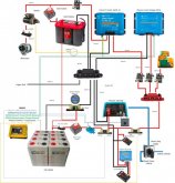
The seperate inverter and charger are both Victron Phoenix's as per the attached schedule.

I got inspired by the threads you have linked to investigate the SBMSO :)

Also I have found the Victron schematic a while ago and used it for inspiration.

Electrical scheme 24V SBMS0 seperate charger+invertor.jpg
 
  • Like
Reactions: Dzl
Little update after one year;

I have installed the system after balancing at home including some test runs. I went for a simple setup without the 230Vac inverter

on the first run I managed to get 224 Ah out of the 8 CALB cells according the BMV700 After bring shut down by the SMBS when hitting 2.7V on a cell high triggered the battery protect.

On board I also installed the Victron Orion Tr DC-DC 30A converter. This enables me to charge the batteries at any time. Normally they are being charged by shore power by the Victron Phoenix smart Charger.

Positives:
- A lot of power to weight ratio. 200Ah is more than enough to cover my needs for coastal sailing, maximum of 2/3 days off the grid.
- I like the fabrication and built Quality of the CALB cells. Not the smallest, but they look tough.

Downsides;
- Complexity of systems required for safe LifePo4 operation such as the BMS including extra wiring, alternator protection.
- The need for a DC-DC charger just complicates things massively. The unit gets very hot when operated at max current. (it does self regulate so that’s great, but not for the peace of mind)

topics to consider:

BMS; this was a difficult choice for me. In the end I chose the SBMS0, Dacian knows his products and the SBMS does what I need it to do. Only downside for me is the fragility of the twisted pairs. During installation I have had issues with the wiring. Completely my fault, but twisted pairs are not really suitable for a sailboat. I am also having trust issues with the I/0 ports. The VictronConnect Phoenix responds perfectly fine to the twisted pairs coming from the SBMS, but the Orion does not unfortunately. Since I do not have to charge the batteries to a 100% i set the charging voltage to 13.8 volts, so I cannot screw up the batteries by overcharging.
 
Thank you for informing us about your real life experience.

While I never have used the electrodacus SBMS0, Dacian sure knows what he is building.

The RX/TX twisted signal cable might pickup too much noise.
One simple way is to use aluminium foil and wrap the wire (or use shielded UTP)

From experience with the DIYBMS others have reported similar issues, where the battery cable from the charger and MPPT controllers seem to give a lot of noise.

In the past I would call it electromagnetic radiation / interference.
For some forum members that automatic gives the association with people wearing tin foil hats...
(Aka crazy)
They don't know how close electricity and magnetism are related.

The noise from MPPT and battery cables are lower frequency waves.
Protecting the source with a finer mesh will work also perfectly, and still allow enough airflow for cooling.

Don't forget to ground the protection, mesh or foil.
It can/will get electric charged.

For marine, CalB make a lot of sense. Safety first, and they are more robust.

In the short time I have played with a boat, I was amazed about the quality that was used, for just about all parts.
Salt water, wind and waves are harsh.
And if the item wasn't Important, it probably would not have been there.

Marine (sailing) isn't safe at low budget.
 
Back
Top