glasdriver
New Member
- Joined
- Jan 31, 2021
- Messages
- 2
My skill level: mostly beginner to intermediate. I understand DC electronics, can use a multimeter and mostly understand lithium cells and the purpose of a BMS. I've installed a solar system in my travel trailer, with inverter, and wired the inverter output through a transfer switch into the trailer's general purpose AC plugs.
A friend gave me a Paxcess 500w solar generator that arrived DOA from Paxcess. I've determined that the main control board is likely defective, but the battery and BMS are working.
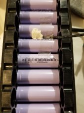
The battery is a 6S 8P array of CMI CR18650 cells and through the BMS I'm able to use the 24v AC charger that came with the unit (wired directly to the BMS) to get the 6S array to charge to 20.80 volts (3.46v per cell). I feel confident the BMS and battery array are functioning as designed.
However, the control board (which contains an embedded MPPT controller) and its accompanying inverter board are not working. The control board won't even pass through the 24V from the AC charger to the BMS. The control board also controls the inverter board and as such, the inverter won't turn on.
What I'd like to do is salvage the unit by striping out the defective boards and adding a replacement MPPT, an inverter and USB boards to the unit to salvage the unit.
I'd really appreciate some recommendations on what I need to purchase to make this happen.
1. INPUT: MPPT controller, able to handle 7 amps, with input either from the 24v AC charger or a typical 17 volt portable solar panel (I have a folding 120w portable panel). Does the MPPT controller need to limit output to 24 volts or can it be a typical 28 volts, and let the BMS manage it from there? The battery pack is not a typical 24 volt array; it's 21 volts from the looks of it. Will the MPPT boost the solar panel voltage to the required 24 volts? If not, what do I need to boost the voltage?
2. AC OUTPUT: Inverter, 500 watts. It would be ideal to figure out how to control the original inverter without the control board, but absent that, what's the recommendation for pure sine wave small inverter that could be fit inside the existing case?
3. USB OUTPUT: I'll need USB outlets. What's the recommendation for a USB panel (2-4 plugs) that would work with this?
4. MONITORING: Battery monitoring system, displaying SOC and watts being consumed or added. Something affordable, even just showing volts and amps used/added.
I can handle the physical parts of the salvage, no problem, but I'd like to have everything fit into the original case (the control facia can be removed and replaced with an aluminum faceplate I can fabricate to fit the original facia). If I can't fit everything into the original case, I have an old Pelican case that would work well.
Many thanks! Here are photos.
Overall unit. The unit will not turn on or off using the controls. The control board and everything on it is useless: MPPT controller, USB output, AC output, solar input, AC charger input -- ALL ARE NOT FUNCTIONING.
EDIT: As this unit arrived DOA, Paxcess supplied another working unit and did not want the DOA unit returned. As such, my other option is to just strip out the non-working stuff and parallel this unit's battery into the other unit (doubling capacity). I'd just install an XT60 on the outside of the case and modify the working unit with a matching XT60, with cable between the two units. Plan B.
.jpg")
Here's the BMS. The XT60 on the right goes to the battery and the cell leads are show to the right of that, along with convenient probe connections. In input to the BMS is to the left, where the red multimeter probe (blurred) is currently inserted, along with output from the 24.1 volt AC charger. Using the charger, I was able to get the battery pack up to 21.0 volts (20.80 resting), or 3.46v per cell (the cells are marked 3.6v).
.jpg")
The inverter board. The XT60 connector show upper left connects into the BMS. It's shown disconnected, as the AC charger is currently connected to where that XT60 would have connected to the BMS (shown partially to the left of the photo).

Here's the backside of the controller board. What I'm referring to the inverter board is more an extension of the controller board rather than a separate inverter, but it sure would be nice to salvage the inverter if I could be controlled manually separate from the controller board.

The front panel. I'll likely fully discard this or possibly just salvage the physical parts of it.

A friend gave me a Paxcess 500w solar generator that arrived DOA from Paxcess. I've determined that the main control board is likely defective, but the battery and BMS are working.
The battery is a 6S 8P array of CMI CR18650 cells and through the BMS I'm able to use the 24v AC charger that came with the unit (wired directly to the BMS) to get the 6S array to charge to 20.80 volts (3.46v per cell). I feel confident the BMS and battery array are functioning as designed.
However, the control board (which contains an embedded MPPT controller) and its accompanying inverter board are not working. The control board won't even pass through the 24V from the AC charger to the BMS. The control board also controls the inverter board and as such, the inverter won't turn on.
What I'd like to do is salvage the unit by striping out the defective boards and adding a replacement MPPT, an inverter and USB boards to the unit to salvage the unit.
I'd really appreciate some recommendations on what I need to purchase to make this happen.
1. INPUT: MPPT controller, able to handle 7 amps, with input either from the 24v AC charger or a typical 17 volt portable solar panel (I have a folding 120w portable panel). Does the MPPT controller need to limit output to 24 volts or can it be a typical 28 volts, and let the BMS manage it from there? The battery pack is not a typical 24 volt array; it's 21 volts from the looks of it. Will the MPPT boost the solar panel voltage to the required 24 volts? If not, what do I need to boost the voltage?
2. AC OUTPUT: Inverter, 500 watts. It would be ideal to figure out how to control the original inverter without the control board, but absent that, what's the recommendation for pure sine wave small inverter that could be fit inside the existing case?
3. USB OUTPUT: I'll need USB outlets. What's the recommendation for a USB panel (2-4 plugs) that would work with this?
4. MONITORING: Battery monitoring system, displaying SOC and watts being consumed or added. Something affordable, even just showing volts and amps used/added.
I can handle the physical parts of the salvage, no problem, but I'd like to have everything fit into the original case (the control facia can be removed and replaced with an aluminum faceplate I can fabricate to fit the original facia). If I can't fit everything into the original case, I have an old Pelican case that would work well.
Many thanks! Here are photos.
Overall unit. The unit will not turn on or off using the controls. The control board and everything on it is useless: MPPT controller, USB output, AC output, solar input, AC charger input -- ALL ARE NOT FUNCTIONING.
EDIT: As this unit arrived DOA, Paxcess supplied another working unit and did not want the DOA unit returned. As such, my other option is to just strip out the non-working stuff and parallel this unit's battery into the other unit (doubling capacity). I'd just install an XT60 on the outside of the case and modify the working unit with a matching XT60, with cable between the two units. Plan B.
Here's the BMS. The XT60 on the right goes to the battery and the cell leads are show to the right of that, along with convenient probe connections. In input to the BMS is to the left, where the red multimeter probe (blurred) is currently inserted, along with output from the 24.1 volt AC charger. Using the charger, I was able to get the battery pack up to 21.0 volts (20.80 resting), or 3.46v per cell (the cells are marked 3.6v).
The inverter board. The XT60 connector show upper left connects into the BMS. It's shown disconnected, as the AC charger is currently connected to where that XT60 would have connected to the BMS (shown partially to the left of the photo).
Here's the backside of the controller board. What I'm referring to the inverter board is more an extension of the controller board rather than a separate inverter, but it sure would be nice to salvage the inverter if I could be controlled manually separate from the controller board.
The front panel. I'll likely fully discard this or possibly just salvage the physical parts of it.
Last edited: