diy solar

diy solar

Samlex: Dual AC and Solar Controller inputs, BMS Controllable, Fully programmable

Steve_S

Offgrid Cabineer, N.E. Ontario, Canada
Joined
Oct 29, 2019
Messages
7,758
Location
Rural NE Ontario Canada
Hello everyone,

I am a recent member to this Forum and have noticed very little knowledge about a certain product line of Inverter/Chargers, namely Samlex who has been in the business quite a long time. They produce quality equipment and can actually save a LOT of hassle & problems encountered by many.

Note: I HAVE NO ASSOCIATION OR AFFILIATION WITH SAMLEX, just a happy customer.

Some Highlights on the various models:
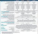
Models Available EVO-2212 2200 Watts 12 VDC, EVO-3012 3000 Watts 12 VDC, EVO-2224 2200 Watts 24 VDC, EVO-4024 4000 Watts 24 VDC, EVOTM models also available in 230V.
* Pure Sine Inverter/Chargers: (2 AC Input) https://samlexamerica.com/products/ProductsList.aspx?cid=S51
* The Charge Controllers: (can use others) https://samlexamerica.com/products/Category.aspx?cid=M6
* Samlex Manual (big, covers all models): Samlex Manual PDF (Covers all models) https://samlexamerica.com/documents/manuals/11025-EVO-2212-3012-2224-4024-0819_Hrez.pdf

Soft Start: The inverter design incorporates “Soft Start” feature with the following advantages and protections:
- When the unit powers up, it starts in Inverting Mode first. The output voltage ramps up gradually from around 48 VAC to 120 VAC in around 200 ms. This reduces otherwise very high starting inrush current drawn by AC loads like Switched Mode Power Supplies (SMPS) and motor driven loads like fans, pumps, compressors etc. This will result in lower motor inrush current (which typically can be up to 650% of the full load current of the motor), which means lesser mechanical stresses, wear and tear and increased lifetime of the motor, coupling and fan. Additionally, the impact on the load side components is greatly reduced, meaning less likelihood of causing problematic voltage drops during starting.

3.16 INSTALLING CONTROL INPUT WIRING FROM LITHIUM BATTERY MANAGEMENT SYSTEM (BMS) TO ENABLE / DISABLE CHARGING OR INVERTING Refer to Section 5.11.2 regarding “Stop Charging” or “Stop Inverting” protections for Lithium Ion Batteries when parameter “BATTERY TYPE” is programmed for Option 2 - “1=Lithium” (See programming details at Section 4.4.2.22.2 in the EVO-RC Manual attached at Appendix A)

The Battery Charger Section of EVO is designed to charge 3 types of batteries - Lead Acid / Nickel Zinc (Ni-Zn) / Lithium Ion. Lead Acid and Nickel Zinc (Ni-Zn) battery charging voltages are required to be compensated based on the temperature of the battery cells. Hence, Battery Temperature Sensor Model EVO-BCTS is required to be connected to the RJ-45 Jack (6, Fig 2.1) as explained at Section 3.15.

Charging voltages of Lithium Ion Battery are not affected by temperature and hence, Battery Temperature Sensor Model EVO-BCTS is NOT required to be used when Lithium Ion batteries are used. The RJ-45 Jack (6, Fig 2.1) can be used to feed control signals from certain Lithium Ion Battery Management Systems (BMS) that may have capability of enabling / disabling “Stop Charging” or “Stop Inverting” control signals for inverter chargers. This control signal is normally generated by the BMS by switching ON (enabling) or switching OFF (disabling) potential free, Drain (+) and Source (-) terminals of mini Opto Isolated Mosfet Switch [Solid-State Relay (SSR)]. Connect the control signal output from the BMS to RJ-45 Jack (6, Fig 2.1) as follows:
• BMS control signal terminal marked “+”: o Connect to any of Pins 1/2/3/4 (Refer to Fig 3.13 for pinout of RJ-45 Jack. Pins 1 to 4 are internally shorted) • BMS control signal terminal marked “-”: o Connect to any of Pins 5/6/7/8 (Refer to Fig 3.13 for pinout of RJ-45 Jack. Pins 5 to 8 internally shorted)

---

FEATURES.jpg
Sam-4.jpg
---
sam-1.JPG
---
sam-2.JPG
---
Sam-A.jpg
---
 
Last edited:
I'm curious to learn more about the "BMS Controllable" aspect of this, does anyone have any experience with this feature or know more about it? I wonder what BMS's can interact with the Samlex inverter/chargers, and in what ways they can interact.

I'm also curious about the pros/cons of the SCC being connected to the system through the inverter/charger.
 
From the current manual

3.16 INSTALLING CONTROL INPUT WIRING FROM LITHIUM BATTERY MANAGEMENT SYSTEM (BMS) TO ENABLE / DISABLE CHARGING OR INVERTING Refer to Section 5.11.2 regarding “Stop Charging” or “Stop Inverting” protections for Lithium Ion Batteries when parameter “BATTERY TYPE” is programmed for Option 2 - “1=Lithium” (See programming details at Section 4.4.2.22.2 in the EVO-RC Manual attached at Appendix A)

The Battery Charger Section of EVO is designed to charge 3 types of batteries - Lead Acid / Nickel Zinc (Ni-Zn) / Lithium Ion. Lead Acid and Nickel Zinc (Ni-Zn) battery charging voltages are required to be compensated based on the temperature of the battery cells. Hence, Battery Temperature Sensor Model EVO-BCTS is required to be connected to the RJ-45 Jack (6, Fig 2.1) as explained at Section 3.15.

Charging voltages of Lithium Ion Battery are not affected by temperature and hence, Battery Temperature Sensor Model EVO-BCTS is NOT required to be used when Lithium Ion batteries are used. The RJ-45 Jack (6, Fig 2.1) can be used to feed control signals from certain Lithium Ion Battery Management Systems (BMS) that may have capability of enabling / disabling “Stop Charging” or “Stop Inverting” control signals for inverter chargers. This control signal is normally generated by the BMS by switching ON (enabling) or switching OFF (disabling) potential free, Drain (+) and Source (-) terminals of mini Opto Isolated Mosfet Switch [Solid-State Relay (SSR)]. Connect the control signal output from the BMS to RJ-45 Jack (6, Fig 2.1) as follows:
• BMS control signal terminal marked “+”:
o Connect to any of Pins 1/2/3/4 (Refer to Fig 3.13 for pinout of RJ-45 Jack. Pins 1 to 4 are internally shorted)
• BMS control signal terminal marked “-”:
o Connect to any of Pins 5/6/7/8 (Refer to Fig 3.13 for pinout of RJ-45 Jack. Pins 5 to 8 internally shorted)

(BMS) will normally have capability of providing potential free relay contact closure signal that could be fed to Inverter Charger to stop charging or stop inverting. For this, the BMS will normally use miniature, Normally Open (1-Form-A), Open Drain Opto-Isolated DC Solid-State Relay (SSR). The Solid-State Relay output terminals in the BMS are normally marked “+” (Drain of Mosfet Switch) and “-” (Source of Mosfet Switch). Example of this type of relay is IXYS Part No. “CPC1002N” (60V, 700mA rating).

The following 2 types of signals are normally used by the BMS for on/off control of charging and inverting operation of the Inverter-Charger:

• “Stop Charging” Signal: In case of (i) over voltage of individual cell / overall battery pack, or (ii) over temperature of individual cell or overall battery pack, the signal will be “enabled” and SSR contacts will close [Drain (+) and Source (-) Terminals will be shorted].
• “Stop Inverting” Signal: In case of deep discharge of the battery to the level of Low Battery Cut Off Voltage, the signal will be “enabled” and the SSR contacts will close [Drain (+) and Source (-) Terminals will be shorted].

If the above two protection functions of the BMS i.e. “Stop Charging” and “Stop Inverting” are to be used for on / off control of charging and inverting operations of EVO Inverter-Charger, the following actions will be required to be undertaken:

a) Programming parameter
“BATTERY TYPE” must be changed from Option 1 - “0=Lead Acid” (Default setting) to Option 2 - “1=Lithium” [See Section 4.4.2.22 of EVO-RC Remote Control Manual attached at Appendix A]. With this setting, the function of front panel RJ-45 Jack marked “Battery Temp. Sensor: (6, Fig 2.1) will change from accepting and processing battery temperature signal from the Battery Temperature Sensor EVO-BCTS to accepting and processing potential free relay contact closure signal from the Solid-State Relay from the BMS to stop charging /inverting.
b) Wiring Connection: Output from the SSR Terminals on the Lithium Battery BMS should be wired to the RJ45 Jack marked “Battery Temp. Sensor” (6, Fig 2.1) as follows:
Connect terminal marked “+” on the SSR (Drain of Mosfet switch inside SSR) to any of pins 1/2/3/4 of RJ-45 Jack (Pinout shown below)
• Connect terminal marked “-” on the SSR (Source of Mosfet switch inside SSR) to any of pins 5/6/7/8 of RJ-45 Jack (Pinout shown below)

• Additional external charging source: Solar Charge Controller of up to 50A capacity. The output of the external Solar Charge Controller is routed through this unit and operates in parallel with the internal charger. The current delivered by the external charge controller is measured in real time. The internal charging current is controlled to ensure that the combined current fed to the battery does not exceed the programmed value of parameter "BULK CURRENT". This improves the life of the battery. Please see Section 5.4 for more details.
 
This is a really neat unit. A couple questions:
1) The manual section 3.16 you ref'ed above seems to suggest that you could use the RJ-45 for the temp sensor OR for BMS signal integration. Is that right? It looks like the BMS integration option reserves use of all 8 wires on the RJ-45.
2) If using the BMS to EVO integration, is it safe to forego the use of relays and BatteryProtects and similar over-charge/discharge relays?
3) What's the catch with routing the solar charge current SCC->EVO->Battery? Do the SCC (Victron SmartSolar) and EVO fight and argue over who is controlling the charge profile and do weird things?
 
This is a really neat unit. A couple questions:
1) The manual section 3.16 you ref'ed above seems to suggest that you could use the RJ-45 for the temp sensor OR for BMS signal integration. Is that right? It looks like the BMS integration option reserves use of all 8 wires on the RJ-45.

2) If using the BMS to EVO integration, is it safe to forego the use of relays and BatteryProtects and similar over-charge/discharge relays?

3) What's the catch with routing the solar charge current SCC->EVO->Battery? Do the SCC (Victron SmartSolar) and EVO fight and argue over who is controlling the charge profile and do weird things?
A 1) Yes that is right, the temp sensor port can be used for ON/OFF signal from a BMS. doesn't use all 8 wires for that nor the temp sensor actually.

A 2) that only accepts the ON-OFF signal from a BMS. here are no protections there as such. That is the BMS' job to do either with relays or internally (pending on BMS type). I cannot answer Victron Battery Protects, I don't use one and don't know. (I am transitioning from FLA to LFP).

A 3) The SCC port is minimally manageable with the EVO and it's internal componentry. It is also limited to a max of 50A input (on the 4024 anyways). It helps to "keep It simple S*" and reduces some extra wiring that would be needed otherwise. SCC still needs DC Breaker between it & solar panels. SCC still has to be programmed appropriately for battery type & profile to use, the EVO does not control the SCC profiles. IF there is solar power & batteries need charge it will pass it forward to charging.

The EVO can be programmed to be a "backup" if the grid goes down so it auto-switches (internally done with a built in ATS). It can be programmed as Battery Power first & if charge threshold reaches "threshold point" it can auto-switch to Grid to charge, OR send signal to AGS port (for Auto Gen Start module) to start a Genset. GenSet & Grid can also pass-through while charging batteries. Switch over is instant.

I use a MIdnite Classic 200 Solar Controller & an attached E-Panel (250A main) between battery bank, SCC & Inverter. This complicates my system somewhat because of how it is setup due to the E-Panel. In my Signature "My System" has some pics (needs to be updatd for the LFP pack going online).

Hope that Helps.
Steve
 
2) If using the BMS to EVO integration, is it safe to forego the use of relays and BatteryProtects and similar over-charge/discharge relays?

A 2) that only accepts the ON-OFF signal from a BMS. here are no protections there as such. That is the BMS' job to do either with relays or internally (pending on BMS type). I cannot answer Victron Battery Protects, I don't use one and don't know. (I am transitioning from FLA to LFP).

Regarding the Victron Battery Protect, I believe it is a glorified solid state relay (SSR). I don't mean glorified in a bad way, maybe 'advanced' or 'programmable' would be a better term.

So I think advice that applies to relays would largerly apply to battery connects as well. In answer to Refinished's question, I suppose it would depend on your system. If you have no DC loads and everything goes through the inverter than it seems like it might be safe to control the inverter directly without the need for a relay/battery protect on the loads side of things. But if you have loads other than the inverter I would imagine you still want your BMS to have the cabability to disconnect those loads.

edit: and I should clarify, Victron Battery protects should not be used between an inverter and a power source.


What's the catch with routing the solar charge current SCC->EVO->Battery? Do the SCC (Victron SmartSolar) and EVO fight and argue over who is controlling the charge profile and do weird things?

A 3) The SCC port is minimally manageable with the EVO and it's internal componentry. It is also limited to a max of 50A input (on the 4024 anyways). It helps to "keep It simple S*" and reduces some extra wiring that would be needed otherwise. SCC still needs DC Breaker between it & solar panels. SCC still has to be programmed appropriately for battery type & profile to use, the EVO does not control the SCC profiles. IF there is solar power & batteries need charge it will pass it forward to charging.

The EVO can be programmed to be a "backup" if the grid goes down so it auto-switches (internally done with a built in ATS). It can be programmed as Battery Power first & if charge threshold reaches "threshold point" it can auto-switch to Grid to charge, OR send signal to AGS port (for Auto Gen Start module) to start a Genset. GenSet & Grid can also pass-through while charging batteries. Switch over is instant.

I've been wondering the same thing as Refinished (whether running the SCC through the Samlex simplifies or complicates things and what sort of managing the Samlex does Re: solar charging). From your answer it sounds like the Evo lets the SCC manage solar charging, and the main purpose of integration is to allow the Evo to manage 'overall charging' which source is primary, etc.

I have a few followup questions:
A. Do you know if the Samlex lets you set a current limit for overall charging

B. I am concerned that running the SCC through the inverter/charger would limit the ability to let the BMS control loads and charging sources separately. I know you use the chargery BMS, are you still able to independently cutoff loads and charging sources with both functions integrated into the Evo?

C. For my application, it would make sense to have the inverter switched off (to save power) much of the day and only turn it on when I need it. This has been one of the reasons I have been hesitant about an integrated inverter/charger like the Evo. Do you have any data regarding power draw of the unit when its just sitting idle, is it possible to turn the inverter portion off without disabling solar charging?
 
Last edited:
A-A) The EVO's are very programmable at every detail. Their docs are HUGE compared to many others but it is all covered in there with tables of info on the settings, I can't / won't post all that here.

A-B) The SCC would be limited to a max of 50A input through the SCC port on the EVO. As have a Classic 200 which can put out 79Amps (24v system) that would hobble it somewhat going through the SCC port. ~BUT~ I just had this discussion with Samlex Tech and my Supplier (who is also an integrator) and as I need to expand my panels etc, I can use an EP-Ever MPPT 60A via the SCC port without issue concurrently. I'm pondering on that as MIdnites can be linked together and share the management interface BUT they are 2x the cost of the EP-Ever.
See 5.4 PARALLEL CHARGING USING EXTERNAL SOLAR CHARGER in manual.

A-C) Without powersave ON, the 4024 only uses 18W standby. With powersave ON (sends a pules every few seconds to detect demand). It is also programmable for wake up & go to sleep thresholds
• 4.8.3.1 Parameter “ENTER POINT” [See Section 4.8.2.2 in the EVO-RC Remote Control Manual attached at Appendix A]
This parameter determines the threshold of power drawn by the load at which the EVO will exit the Normal Operating Mode (full 120VAC output voltage; No Load Power Draw from the battery will be 25-30W) and “enter” Power Saving Mode (output voltage consisting of 3, 60 Hz cycles of “reduced 48VAC load search voltage” every 0.5 sec; No Load Power Draw from the battery will be < 8W).
The programmable range of this parameter is 4-50Watts; Default value is 6W for EVO-2212 / 2224 and 8W for EVO3012/4024.
 
Regarding Victron Battery Protect:
From another thread BUT It answers important questions.

Justin Laureltec said:
Very important to note: A Victron BatteryProtect can NOT be used to disconnect the main DC line feeding an inverter... this has been covered to exhaustion on this forum, and is reflected in the updated user manuals available online from Victron. The only manufacturer-supported way to do this (read: the only way that doesn't void your warranty) is to use the BP to trigger the remote on/off of the inverter if so equipped.

The BP can be used to disconnect a charge source if the BP is connected in reverse - that is, with the charge source connected to the "in" post and the battery connected to the "out" post. Given that the BP is unidirectional in operation, any current from Out to In must not be permitted under any circumstances - this is what's meant by "reverse current". Current MUST NOT flow from "out" to "in". Failure to ensure this can result in a very high danger of fire or external component damage.
 
I ordered a EVO-2224 and while it was in transit I got deeper into the documentation. The manual goes into great detail on the charging of lead acid variants. The Lithium charging section is far shorter and seems to suggest that the BMS integration contacts should be used for managing Lithium charging. I was planning on using the 'normal' charge stage management of the unit with a Lithium-friendly charge profile along with the Stop Inverting/Charging contacts as a BMS managed backup. All current in/out of the battery bank would route thru the EVO. would be routed thru the EVO. They sent me a EVO-2224E, which is the wrong model and has to go back for return. So, now I am second guessing my purchase since I have the option to not reorder this unit.

1) Are you using it to charge Lithiums without the BMS contact closures and is that working as desired? Which profile are you using?
2) Also, I don't see where the unit can provide any sort of SOC in a fuel-guage or percentage format. Am I missing something? I got the 'Plus' version of the remote.

Thanks for your insights.
 
Well the E for Europe Model isn't good for US/Canada. just an oopsie on whoever you bought from.
The inverter / remote does not show SOC/DOD, get that info from the BMS on the pack itself. If you have multiple packs in parallel then another gauge is needed for the entire "bank of packs" I small unit with a hall sensor is good for that, like the DROK's.

I am running split with LFP on one side & FLA on the other. At this time the Inverter's charger is setup to charge the FLA bank till I can decommission the FLA, although I can program the LFP stuff in and save it to a profile on the SDHC card and just swap that when needed. My system isn't and won't be conventional in a few ways so I have to work around some things and make some compromises while I am transitioning. If you look at My Setup (see signature) it shows a bit of the confusion going on.... the info there is transitional too.
 
From a different thread:
There IS a gotcha there though too... IF you have more than one LFP Pack and so more than one BMS you need an intermediary to manage all the BMS' & the interaction with the Samlex. This can be done using the Modbus protocol (Samlex has Modbus & CanBus) via a Raspberry Pi running Modbus software programmed to interact with it. Samlex does NOT publish the Modbus protocol stack, it requires a legal NDA, I am not sure about the CanBus protocol. (I have the Modbus protocol info as I am a developing software to work on my systems management package.)
I was thinking about this. Since the 'all is well' state is normally open, why can't the leads from the BMS FETs be combined? If all BMSs are happy, the circuit is open and the EVO keeps working. If any of the BMSs close the circuit, the EVO detects continuity and stops what its doing. No?

BTW - The correct EVO showed up and it lacks a Battery Type and Charging Profile options in the menu. I assume this is a firmware version issue so I called Samlex. I assume I can update this via the SD card slot.... Wonder if I might hear back over the weekend...
 
Last edited:
From a different thread:

I was thinking about this. Since the 'all is well' state is normally open, why can't the leads from the BMS FETs be combined? If all BMSs are happy, the circuit is open and the EVO keeps working. If any of the BMSs close the circuit, the EVO detects continuity and stops what its doing. No?

BTW - The correct EVO showed up and it lacks a Battery Type and Charging Profile options in the menu. I assume this is a firmware version issue so I called Samlex. I assume I can update this via the SD card slot.... Wonder if I might hear back over the weekend...
If one BMS goes to error, the others do not, the individual pack needs to either disconnect or what have you pending on the case. It has to be independent for the others. It's the topology of how things get setup.

Firmware is done via the SDHC card, 16/32GB, once you get it it's simple enough to do. Logging also goes to that card and default is 1 second. You can also save your config profile to it.
 
For anyone who follows, do update the firmware if you get one of these units. My new unit was pretty far back level and quite a few settings in the included manual didnt match. Unsure how a unit with old firmware and a much newer manual ended up in the same box. The engineers are also continuing to add features via firmware, not just fixing and enhancing existing ones. So far, this thing is running very predictably.
 
@Steve_S Just wondering about how noisy the fans are? Could this be mounted in a living area without being too objectional.

I realise this is a subjective question ..... but interested in your opinion.
 
@Steve_S Just wondering about how noisy the fans are? Could this be mounted in a living area without being too objectional.

I realise this is a subjective question ..... but interested in your opinion.
Subjectively, I would not want this thing in a room that I spent a lot of time in. The fans are speed controlled, so they can be off or low, but when they are on any speed, they are not really quiet. I was charging at a 15 amp rate in a 67 degree room all day Sunday and the fans ran 75% of the time.
 
Interesting discussion. I'm deciding between Evo 2224 and PST 2000-24. Still not sure what to pick. I like the more advanced Surge output power management of EVO, besides other functions that PST doesn't have. It's pretty bulky too, 3 times weight of PST series, which is less appealing, same as fan noise if used with connection to a SCC.
One other thing I also like is Power saving no load consumption of only 8W, and efficiency is also better than PST. Decisions decisions....
 
Last edited:
Remember the EVO's are Pure Sine Low Frequency and a lot of the weight is in the Big Assed Coils ! And they are Hefty !
I had ONE issues once, and Samlex didn't even blink, they swapped out the whole unit because it was the most effective & efficient thing to do. Their support has been great too, I like dealing with their techs & engineers... but I have other interactions with them over software dev and such so.....

Thing is, look seriously at just HOW configurable the EVO's are.... a LOT on Inverter / Charger units are nowhere near that "tweakable" ! Unfortunately, it means actually RTFM ! No Guess Work, lot's of reading the Big Thick Manuals and sticky notes to highlight sections / spots...
 
You're right, for whatever unforeseen future expansion it would be better to pick EVO model. The way I'm using my solar system right now is a power backup and also my home office is powered by it. I have a few low current DC devices that run 24/7 and some AC equipment that's plugged in and on standby. I do have an ATS right now and I'm switching off my inverter with an Automation HAT relay on RPi, based on voltage of the battery. So I'm pretty much covered with functionality I need at the moment. But now when I'm going to switch from 12V to 24V I need a new inverter and will be spending money. So this is the time to make a right decision. Either way I'll be fine, whether EVO or PST, but it's hard to pick.
Not to mention RF noise issues with HAM radio equipment, but I think these two Samlex inverters should do fine with this regard. Although, EVO being low frequency might be better.
 
Back
Top