diy solar

diy solar

Sanity check a novice's small solar plan.

Dustin Henderson

New Member
Joined
Nov 2, 2022
Messages
17
I have a RV trailer on which I am going to add a modest solar set up for the purpose of recharging the LifePO4 on board battery for the occasional day or two of boon-docking. Most of my time is spent on FHU, but sometimes we have an over night stop without power, or a weekend in the forest (where I use a portable panel and run the generator for A/C and when needed). I have a 100Ah battery which has never presented a problem because of our minimal use, but I do worry I might run out of juice to power the landing gear or slides or lighting or furnace fan which would force me to fire up the Honda (not a big deal) on a quick overnight.

So, I am going to install a couple hundred watts on the roof. I am going to start with a single 200 Watt panel (eg Rich Solar). I will wire in a Victron SmartSolar MPPT 100/30 because I like the bluetooth and app interface and hear good feedback and don't mind the premium over a budget controller. I will add a shunt or appropriate battery monitor. The trailer is wired for solar (10 AWG?)with MC4 connectors up top. I plan to put the SCC somewhere near the battery rather than inside. Hope I can find the wires …


Future Considerations: This trailer is not my long term RV, and I will never be integrating an inverter in to the core electrical system. However, I could envision going to 200+ Ah of battery, and I probably envision adding another 200 W panel (maybe sooner than later on that one. There is not a ton of convenient space for more so 400 is probably the max, or maybe 600. I may at some point choose to put a small/cheap 1000W inverter in for charging purposes and occasional plug in of light loads, but not wired in to the RV electrical.

Questions that come to mind:

Is the panel I speced out* sufficient to meet the draw demands required to kick off the MPPT? I am looking for higher VOC panels to make sure I have head room.

When I add another panel, I assume I may want to go parallel (depending on answer above) because shading and the flat panel placement are not ideal. Does that make sense? If going serial I think the MPPT still has plenty of room to handle another panel.

Where do I need to put fuses? What types of fuses?

Where to add cut off switches? I have only added one to my battery for a true battery cut off. I presume I want another one (two?)


What cabling specs are needed and where given my modest future considerations?. Again, this is prewired by go solar and I think they are all awg10. I am not going to pull new cable for this little system.

Thanks for any help.

*Rich Solar 200W
  • Maximum Power(Pmax): 200W
  • Maximum Power Voltage(Vmp): 20.4V
  • Maximum Power Current(Imp): 9.80A
  • Open Circuit Voltage(Voc): 24.3V
  • Short Circuit Current(Isc): 10.2A
  • Maximum System Voltage(Vmax): 1000VDC
  • Temperature Range: -40°C ~ 90°C
  • Max Series Fuse Rating: 20A
  • Weight: 26.5 lbs
 
Is the panel I speced out* sufficient to meet the draw demands required to kick off the MPPT? I am looking for higher VOC panels to make sure I have head room.

IIRC, The Vic requires [actual bank voltage + 5v] to start MPPT, and only +1v (?) to stay running after that. The panels' Voc should suffice for this.

When I add another panel, I assume I may want to go parallel (depending on answer above) because shading and the flat panel placement are not ideal

In this scenario most will recommend parallel.

. Does that make sense? If going serial I think the MPPT still has plenty of room to handle another panel.

A 30A MPPT is well-matched to 400w of panel, regardless of their wiring arrangement. For the reasoning behind it, see the Oversizing a PV array section of this Victron article. They discuss overpaneling to 130% of controller rating, while the proposed 30A/400w setup is milder at ~111%. My own setup is 125% and I rarely get near the controller's rated max.
 
On my RV I have two 320 watt panels on the roof. They are wired in series. My experience has been if one panel is shaded, so is the other. Series was a simple wiring configuration. No Y connector needed. Not that Y connectors are expensive, but it was one less thing to buy and install.

I have two 320 watt panels for on the ground also. I wired these in series also since I place them side by side pointing the same direction.

My newest addition is a set of four 280 watt panels that I mount on a small ATV trailer. These I wire 2s2p because I put one 2s set oriented for AM sun and the other 2s set for PM sun.

The first two setups use Victron 100/50 solar charge controllers. The last set uses a Victron 100/20 because I don't need any more than 20 amps of charging for what I use it for.. I could get by with just two panels, but I stuck with all four just because.
 
Thanks for the feedback!

Would anybody like to describe where and what specific kind of fusing is needed, and what gauge cable is needed?

200w(400w planned) --->10AWG--->MC4 gland--->10AWG---> Victron SmartSolar MPPT 100/30---> ??AWG---> LiFePo4 --->??AWG---> (future 1000w stand alone inverter)
 
Wire gauge is dependent on three main things: amps, volts and length. When you know those three things you can plug them into a wire gauge calculator like the one linked below.


On my 100/50 solar charge controller I used 6 awg on the output side.

It is recommended that you put in a disconnect between the panels and the solar charge controller. That allows you to turn off power on the input side of the solar charge controller so you can work on it or the rest of the system. Always turn off PV power to the solar charge controller first, then disconnect the battery side. Many of us are using dual pole DC circuit breakers for this "disconnect" switch. Be sure it's rated for DC! I mistakenly ordered AC breakers for my initial install and had to go back and replace them with DC breakers.
 
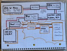
Attached is maybe the crudest napkin diagram seen on the forum. Hope you can decipher it, feedback please.

Notes:
  • The orange is future state
  • I have gone back and forth and do believe I will eventually wire panels in Serial, and probably sooner than later.
  • I have specced 6AWG for the short and relatively low current wiring. I admit I am sometimes surprised to see people recommending 2/0 or something similar for such a modest set up.
  • Note also I have specced Circuit breakers (rather than fuses) for the same reason. My perception is they are perfectly sufficient for this system but would like comments on the same.
  • For the "future state" portion, I do have questions on AWG to use. Again all runs less than 4 feet. In fact more like 18". 2 AWG?
  • Again, for the "future state" portion, Do I need busbars? Max will be two lugs of not.


qfthde.jpeg
 
Bus bars are a good idea. It makes the wiring easier. The bus bars are still in the DC system, so the breaker between the bus bars and the inverter also needs to be CD (not AC). Be sure the bus bars are copper, not brass.

A 1000 watt inverter should pull 98 amps, max. (1000 watts / .85 inverter efficiency / 12 volt low cutoff = 98 amps). Add a 1.25 fudge factor on the over current protection and a 125 amp circuit breaker or fuse is about right.

2/0 cable is likely overkill for between the bus bars and inverter or between the LiFePO4 bank and the bus bars. The wire size calculator I use says you could get by with 6 gauge for a 2.03% voltage drop, assuming 100 amps over 6' (round trip) at 12 volts.

You can find 125 amp circuit breakers. Be sure they are very good quality. For this, I would use Cooper Eaton Bussman breaker.

Except for the PV circuit, you need to have over current protection on only the positive cable. This applied to downstream of the solar charge controller and between the bus bar and inverter.

Every negative circuit must be wired to the bus bar. You must not attach anything - other than the shunt - to the negative post of the battery. Otherwise, the shunt can't do its job properly. All positive cables should also go to the bus bar, with a single cable between the battery and the bus bar.

Given the distance between your solar panels and your solar charge controller, wiring your panels in series may be required, not optional. The higher voltage will allow you to use a smaller wire. In parallel, you'll have a 3.46% voltage drop. In series, it's only 1.73%. That assumes 10 amps at 48 volts over 80' of wire (round trip).
 
Bus bars are a good idea. It makes the wiring easier. The bus bars are still in the DC system, so the breaker between the bus bars and the inverter also needs to be CD (not AC). Be sure the bus bars are copper, not brass.
Thanks for all the help. Sure bus bars make things easier ... but in my system ... I am not really connecting multiple wires, other than minimally in the future state. If ever there was a case for not needing them, this may be it.
Except for the PV circuit, you need to have over current protection on only the positive cable. This applied to downstream of the solar charge controller and between the bus bar and inverter.
gotcha.
Every negative circuit must be wired to the bus bar. You must not attach anything - other than the shunt - to the negative post of the battery. Otherwise, the shunt can't do its job properly. All positive cables should also go to the bus bar, with a single cable between the battery and the bus bar.
yep .. tried to show that on the diagram, not suprised i was not clear.
Given the distance between your solar panels and your solar charge controller, wiring your panels in series may be required, not optional. The higher voltage will allow you to use a smaller wire. In parallel, you'll have a 3.46% voltage drop. In series, it's only 1.73%. That assumes 10 amps at 48 volts over 80' of wire (round trip).
This is what i was thinking. 30' is an estimate based on the prewire ... it is possibly shorter, but why i am leaning to series and also 'sooner than later'.

thanks!
 
A minor update for those following at home ... and some are not going to like this....

I have started acquiring supplies with hopes of a January installation. In this process I had come across an opportunity for some Renogy materials that presented too good a value proposition to pass up. Namely some 100W panels and 40A MPPT controller. While less "efficient" the smaller panels will also give some layout flexibility the larger panels did not provide. I will be starting with 2x100 in Series. Upgrade path would be to 3 x100 in series then 2s2p.

So, in a couple weeks I will create a new build diagram reflecting actual materials on hand.

Regarding Renogy, let me say I have a few of their mass market products already (Suitcase Solar and controller, mini charging station, etc) and I have never had an issue with any of it. In fact the little suitcase works surprisingly well. I am aware not everyone has the same experience or perception. Delivered and out the door at $.62 a watt for new spec panels was hard to pass up.

Maximum Power at STC: 100W
Cell Efficiency: 22.00%
Optimum Operating Voltage (Vmp): 20.4V
Open-Circuit Voltage (Voc): 24.3V
Optimum Operating Current (Imp): 4.91A
Short-Circuit Current (Isc): 5.21A
Operating Temperature: -40°F to 176°F
Maximum Series Fuse Rating: 15A
Certifications: CE, ISO
Maximum System Voltage: 600V DC (UL)
Weight: 14.1lbs/6.4kg
Dimensions: 41.8 x 20.9 x1.4 in
 
Yikes, this project has fallen off my to do list and needs to get back on it. Finding the rest of pre wired in my trailer will be on the list this week, although I think I found some 8 AWG near the battery compartment which is probably it. (I had assumed 10 incorrectly).
 
Back
Top