diy solar

diy solar

SCC settings for LiFePO4 battery (new approach for me)

RandyP

Solar Enthusiast
Joined
Sep 21, 2019
Messages
742
New approach to setting SCC voltages for LiFePO4 battery.
I came across this You Tube channel,
'Off-Grid Garage'
and have watched several of the videos there.
I discovered this info. Its new thinking for me.
https://www.youtube.com/watch?v=6vTaCkTVl7I
Armed with this bandwidth concept between Boost/Absorb charge voltage setting and Float voltage setting and loss of solar energy when the SCC is operating in this band I went out and changed my SCC boost/absorb and float voltages to both be 13.8 v. In addition to these two changes as suggested by the video above, I changed my Boost charge return voltage to 13.8 (I am using a Renogy SCC and it requires this additional voltage setting).
The result was prenominal !
Yesterday I played with the SCC in full sun and was only able to get about 300w power thru the SCC to the battery & load. Had the boost/absorb voltage at 13.8, the float at 13.7 v and the Boost Charge return set to 13.3 v.
Today, with good sun, and the three voltage settings at 13.8 v, by varying the load on the battery, I was able to get just under 400 watts thru the SCC to the battery/load. After the battery was sufficiently discharged by increasing the load beyond the capacity of the SCC float voltage power production max, the battery started mppt charging (Boost charging) and maintained the 400 watt SCC output level. Removing the load from the battery at that point, the battery fairly quickly recharged on Boost/Absorb to the set Boost/Absorb voltage and settled into Float charge with 0.0 amps going into the battery.
 
Which kind of shows how SCC's designed for lead-acid and using that lingo suddenly need all these workarounds to emulate his desired CV of about 3.45v / cell in his case for LFP.

But cool - I forgot if he mentioned that when using LFP, be sure to disable any sort of temperature-compensation, which is not needed with LiFeP04. That can be overlooked sometimes when using lead-acid based SCC's.
 
Last edited:
Seeing no response, [EDIT: now I see there was one good response, thank you] I searched some more and found this:
This write up is centered around LiFePO4 charging and its challenges.
Here's a synopsis of the article:
"Lithium iron phosphate (LiFePO4) battery banks are quite different from lead-acid batteries and this is most apparent when it comes to charging them. Lithium battery banks charge much more easily and overcharge just as easily. They degrade gradually when kept full for extended periods and can develop memory issues when cycled inadequately."
"Can develop memory issues when cycled inadequately" is of interest to me. This statement supports operation of a LiFePO4 battery without fully charging the battery. But I was not aware of this memory problem. Apparently operating the battery in a narrow bandwidth as described on my original post above could be detrimental to the battery.
There is much detail in the entire article. When I read it I found areas of concern I was not aware of. Chargers being used as regulators with input from a shunt device at the battery to turn them off at the appropriate battery charging tail current level...loads on chargers trick them to thinking they have not saturated the LiFePO4 sufficiently because the measured tail current includes any load current that may be on a battery and loads can very over a charging cycle....
 
Last edited:
WOW - as a prolific WOT wall-of-text writer myself, that guy has overcomplicated the whole thing.

Analysis:
A design firm trying to introduce LFP to those coming from the background of lead-acid, uses terminonlogy recognizable to them, and uses so much, that the reader probably comes away thinking "I better let the design house handle it".

Consider your mind blown. What you have done with your work-around settings in your SCC is to discover that all you need with LFP is the bog-standard CC/CV.

In fact, my recent Genasun is built that way. Only has a built-in CV setpoint. Nothing for me to do or analyze.

All those tail-current complications and formulas presented simply mean this guy should not have bought such a low-capacity bank to have to charge to full each and every time. :)

Remember that you are not a full-blown marine system. This design house is competing against places like Lithionics and brings up issues (that may be completely wrong if taken out of context) that really don't concern you or me.

One day you'll realize that charging LFP is not hard or mysterious at all - as long as one doesn't use lead-acid terms! I remember that day well myself. :)
 
Last edited:
I went back and watched all the Battle Born videos with the CEO Dennis presenting their batteries, developing FAQ videos. And as I had remembered and was confirming, Denis repeatedly indicates that their 12v 100 ah battery should be charged to 14.2 v absorb with 10-15 minute time held at that voltage. The reason given is to allow the cells to top balance. Apparently very important to Dennis. Then a 13.6 v float can be be applied if I think it’s necessary.

Then I went back to Off Grid Garage and read about using Raspberry pie mini computer to monitor /communicate Victron device data to the phone app. Interesting.
 
Last edited:
My Genasun is set for 14.2v for much the same reasons. But since float is not necessary with LFP, it has none.

Many lead-acid based SCC's have a float-mode, which can't be disabled. Reduces consumer confusion with LFP to just somehow deal with it because they can't turn it off! I know why BB talks about float, but consider that 99% of the customers will be using basically lead-acid based SCC's with it, or other vehicular chargers with float. You don't want to scare them off.

Actually, it has more to do with the possibility that someone will leave a BB in the garage for 2 years neglected, and even though LFP has very little self-discharge, it does happen over time. A weedy battery tender with a float will catch the self discharge in time rather than stopping at the BMS LVD.

So just be careful. Some recommendations that read like gospel, may just in fact be trying to protect customers that are only familiar with lead-acid, or try to treat their LFP bank like one with lead-acid type gear. Not that it's bad - on the contrary! It's good business.

Not everyone can be a battery nerd like we are here on this forum. Normals don't come here. :)
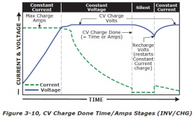
So your Gensun SCC is set for CC charge untill the battery voltage is 14.2 v.
-Does it have a CV setting after that ?
-Any min time setting at that CV setting, any tail current setting ?
-What is the Restart voltage setting or differential below the CV setting that initiates another charge cycle, or do you use SOC ?
And in your last sentence did you mean to use the term 'Normals' or 'Morals' or 'Mortals' ?
 
Nope, the generic mppt Genasun for LFP is hard coded at 14.2v. If one has a more specialized need then they can simply custom order for a different voltage limit. Just a CC/CV. Nothing to set. Just hook panel and battery up properly and done. No other concerns.

They don't offer large-current controllers, although I suppose if one was in love with them, you could do multiples on a single battery ... but errr.. yeah that's a different decision to make.

Normals - heh, no that means people more interested in camping or whatever with their batteries than trying to figure out "Wait, you guys spent 5 years arguing about something called top-balancing? Isn't that vertigo? You guys need to go to the doctor!" :)
 
Substrate, your approach is simplistic to a point of not knowing how that Gensun SCC works. I like the fact that it is made in the USA. That's about it for me. The CC/CV term you used without understanding what your SCC does in the CC/CV mode demonstrates that to me.
You are using that very low energy SCC to charge a very small lifepo4 battery to be used to operate radio equipment in remote areas.

I am using my SCC, DC to DC charger and Inverter/charger to charge 300AH lifepo4 battery that power up a microwave, hair dryer, insta-pot, or even a roof AC in the hybrid mode with a honda 2000i inverter generator. I think my interest in charging my lifepo4 battery to maximize SOC at the end of the solar day while at the same time powering variable loads during the day drives me to learn more about lifepo4 battery charging. Extending the life of my lifepo4 (or at least not shortening it) by using a reasonable CC max voltage cutoff point also interests me.
 
Last edited:
I do understand but that's cool.

Questioning each other's depth of knowledge is the first sign that you've joined the club! Welcome aboard - there's no turning back! :)

In time, you'll find out that a holy-grail, one-setting-fits-all may not be the best fit for your application, and you'll modify those recommendations based on your own experience and for the applications you are using at the time.

You'll see. It's fun. Gurus can guide you, but ultimately, its your choice.
 
Last edited:
I got it. Thanks for being patient and polite. Not my virtues. Sorry.
 
Not sure I grasp the motivation. In post 1 there seemed to be a concern about solar harvest. If you let the battery run down the harvest comes the next day. Then post 3 there was a concern about shallow cycling and holding full charge too long as it relates to battery longevity.

I keep thinking it would be best to cycle the battery close to 60% give or take. Depending on usage and battery size it would seem you could turn the solar off a day or three before you let the solar run the charge back up near full even if that takes a few days.

I am partly thinking to charge 13.6/13.8 max and set the equalize to every 10/30 days to hold 14.2 for 30 minutes. Float I think I want low to basically turn the solar off and let the battery cycle.

The whole top it off daily seems like a lead-acid hang over.
 
@RandyP - no worries. You're describing me as well! :)

That's another cool trick though - in some threads you gotta' keep a thick skin, because sometimes there's a hidden gem.

None of us are professional orators, or masters of a text-based comms system, least of all me. You should have seen the old computer days of Usenet!

Onwards! Check out those other things you wanted to look into, but keep your armor on! :)
 
Not sure I grasp the motivation. In post 1 there seemed to be a concern about solar harvest. If you let the battery run down the harvest comes the next day. Then post 3 there was a concern about shallow cycling and holding full charge too long as it relates to battery longevity.

I keep thinking it would be best to cycle the battery close to 60% give or take. Depending on usage and battery size it would seem you could turn the solar off a day or three before you let the solar run the charge back up near full even if that takes a few days.

I am partly thinking to charge 13.6/13.8 max and set the equalize to every 10/30 days to hold 14.2 for 30 minutes. Float I think I want low to basically turn the solar off and let the battery cycle.

The whole top it off daily seems like a lead-acid hang over.
Thanks for the recap and summary. I guess I'm presenting ideas about solar charging LiFePO4 battery in an unorganized way.
Solar Harvest was my first concern. If I end a solar day with more SOC in the LiFePO4 battery, then I can go more days without solar, as in days without much sun. I know that LiFePO4's DO NOT require a daily recharge to 100% SOC like lead acid batteries (sulfating).
And apparently holding them in a narrow bandwidth of SOC (Voltage) is detrimental to the battery. There is also the Nordkyn thought LiFePO4 battery "Can develop memory issues when cycled inadequately".

I had just developed the idea of using the lead acid charger feature 'Equalizing' on the LiFePO4 battery once weekly at 14.2 v (15-20 min) for top balancing and see that you too are considering that charging technique also. Encouraging to me.

My battery is a parallel set of three BB 12v 100 AH batteries. They are composed of about 120 cylindrical cells each. The idea to use three BB's in parallel comes from wanting to use a 3 KW hybrid inverter/charger. It takes about 300 A 12vDC to operate that inverter at full power, and the three BB batteries are rated to deliver that ampacity, however my battery would only last one hour at that rate of consumption. .
I see that most are building their own Prismatic cell batteries.

It could be that considerations for LiFePO4 Prismatic cell battery charging voltages are different than for LiFePO4 Cylindrical cell batteries.
 
Last edited:
I have a Magnum hybrid inverter/charger. I could use CC CV charging with the small Honda 200i generator to charge the battery up when/if its solar charge gets too low.

1622667195804.png
 
I have a Magnum hybrid inverter/charger. I could use CC CV charging with the small Honda 200i generator to charge the battery up when/if its solar charge gets too low.

View attachment 51346
For what its worth, these are the setting I've been using for the past 5 years. Magnum 3000w hybrid inverter/ charger, Magnum PT100 SCC, ME-ARC50. The scc follows the exact settings that the inverter/ charge is set for. When on occasion I use either the Honda eu2200i or a eu2000i generator I'll set incoming loadshare to 15a and charge at 100a.

If on shore power I'll turn off the charger (on the inverter/ charger) and use only solar to top off the batteries and then float:eek: , depending on the furnace run time during the night nighly consumption is 25-35ah or 5-7% DOD.

Favorites (can be changed to personal taste)
F1_ Bat amps - PT ADC (present be produced)
F2_ AC output - 121 VAC/ 60.0 HZ
F3_ AC input - Amps= 15a (adjustable with incoming power)
F4_ Load amps - 0 amps AC
F5_ AC Amps - -2 amps

CRTL
01_ AC in Control - Auto Connect
02_ CHG Control - Multi Stage
03_ Gen Control - Off
04_ PT Control
• a_ PT Chg CTRL 1 - Multi Stage
• b_ PT Aux Relay - Control= Disengage
• c_ PT Alarm - Control= Off
• d_ PT Mppt Ctrl - 15 min sweep

METER
Inverting_ DC (present time reading)


01 DC Meters
• a_ DC volts (present time reading)
• b_ DC amps (present time reading)
02 AC Meters
• a_ AC output (present time reading)
• b_ Load amps (present time reading)
• c_ Input AC (present time reading)
• d_ Inv/ Chg amps (present time reading)
• e_ Input AC1 (present time reading)

SET UP
01 System Set up
• a_ Set Clock
• b_ Screen set up (press select) _ Brightness (50%), Contrast (100%), Power save (1 min)
• c_ Temp select - Fahrenheit
• d_ Max charge- Amps 200 adc
• e _ Link PT Chg - setting - yes

02 Inverting/ Inverter set up
• a_ Search watts - Off
• b_ LBCO setting - 12.0 vdc
• c_ AC In time - 6:00am-6:00pm
• d_ AC In VDC - 11.O-14.1 vdc
• e_ AC In SOC - 80%-100% SOC
• f_ Power up - Always off

SET UP INVERTING
03 Charger Set up
• a_ AC Input - Amp= (can be set to available shore power/ generator incoming power)
• b_ VAC Drop out - 80 VAC
• c_ Battery type - Custom (with in here absorb voltage can be adjusted)
• d_ Absorb done - Time= 0.1 hrs (minimum, can't be turned off)
• e_ Max charge - Rate= 100%
• f_ Max charge - Time= 12.0 hrs
• g_ Final charge - Stage= Multi
• h_ EQ Reminder - Days= Off

04 AGS SET UP - No AGS Present
05 BMK SET UP - No BMK Present

06 PT SET UP (Magnum pt controller follows Magnum inverter settings)
• a_ Battery Type - Linked
• b_ Absorb Done - Linked
• c_ Maxed Charge - Rate= 100%
• d_ Max Charge - Time= 12.0 hrs
• e_ Bulk Start (press select)
- select Bulk Start, Daily / sun up= yes
- set Bulk Start, Volts= 12.0
- set Bulk Start, SOC= 80%
• f _ PT Aux Relay - 10.0 to 14.0
• g_ PT Alarm - 10.0 to 14.0
• h_ Power Save PT - Display= 15 min

TECH
01 Temperatures (press select_ scroll)
- Inv BTS (present time reading)
- Inv TFMER (present time reading)
- Inv FET'S (present time reading)
- AGS Sensor 0ff
- ACLD Temp 32f
- PT BTS (present time reading)
- PT Inductor (present time reading)

02 Versions (press select_ scroll)
- Inverter: 1.2
- Remote: 4.0
- AGS: 0.0
- Router: 0.0
- ACLD: 0.0
- PT: 1.1

03 Inv Model - MSH3012H (3000w hybrid)
04 Fault History
05 Set up pin
06 Ext Control - No ext control
07 Show all - Menus= No
08 Load Defaults

The following parameters are for programming the ME-ARC Version 4 advanced control.
Setup 02B LBCO Setting: Volts = 12.0
Setup 03C Battery Type: = Custom
Set Absorb Volts: = 14.1v or 14.2v (depending on season)
Set Float Volts: = 13.6
Set EQ Volts: = 14.1
Set EQ Done Time: = 0.1
Setup 03D Absorb Done Time: = 0.1 (minimum)
Setup 03E Max Charge Rate: = 100%
Setup 03G Final Charge Stage: = Float
Thank you for the reply and info.
Have you considered adding a BMK with shunt to your magnum equipment to enhance battery charging current cutoff point ?
Just a point of reference, my Magnum Inverter/Charger is a MSH3012M (M is for mobile) model.
 
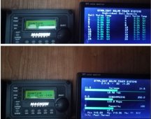
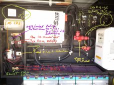
Same inverter that I have been using. I don't need the bmk, there is a shunt being used but with my GBS system. GBS display shows me everything I want to know. The Magnum remote shows me everything else toggling through the buttons, solar production, ac/ dc info.

Magnum equipment first line of protection, GBS system 2nd line of protection.
Displays...
20171130_094317-COLLAGE.jpg
System..
20200318_080203.jpg
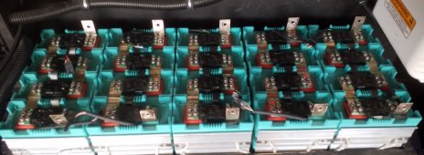
Batteries..
20200126_101803.jpg
 
Last edited:
The BMK communicates with the MSH reporting exact current to/from Battery only. Without the BMK, the MSH uses its charger output current to make decisions about battery charging.
 
Last edited:
Back
Top