• Have you tried out dark mode?! Scroll to the bottom of any page to find a sun or moon icon to turn dark mode on or off!

diy solar

diy solar

Schneider 100A, 600vdc MPPT charge controller breaker questions

pvdude

Solar Addict
Joined
Feb 8, 2021
Messages
734
Location
Florida
I need some advice on the current ratings for these breakers.
The vendor I bought the equipment from has no idea.
The issue is that I have a Schneider 100A, 600vdc MPPT charge controller.
This seems to be a new Schneider product, probably why they don’t know anything about it.

The Schneider documentation is not up to date, all they have is the listing for the old 80A, 600vdc and 60A 150vdc charge controllers.

The installation manual has the PV array + routed through a breaker, and the DC battery output routed through another breaker.
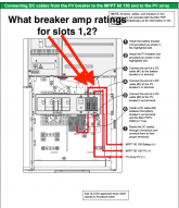
breakersinslots1-2.png
I know the breaker for the PV must be 600vdc, not sure about the amp rating to look for.
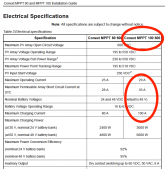
Do I use the “Maximum Permissible Array Short Circuit Current at STC”? (35A)
So possibly a 35A, 600vdc breaker?

For the battery charging breaker Schneider shows a 100A, 125vdc breaker for the smaller 80-600 MPPT charge controller.
So possibly a 125A, 125vdc breaker would be OK for the 100-600 model I have?
schneider_breakers_for_smaller80-600.png
Schneider MPPT 100-600 electrical specs.png
 
If your MPPT can output 100 amps, putting in a 100 amp circuit breaker on the output side is probably undersized. You want something that isn't going to trip if the MPPT really gets going and outputs the full 100 amps. The fudge factor that I've seen used is 25%, so a 125 amp circuit breaker is what you want.

Follow the same rule on the PV input side.
 
Thanks, I ordered a 125A for the battery connection.
Screen Shot 2021-04-12 at 14.22.34.png

No searching thus far has found a 35A, 600vdc panel mount, single pole breaker for the PV side, however.
Seems odd.
 
No searching thus far has found a 35A, 600vdc panel mount, single pole breaker for the PV side, however.
Seems odd.

In that case, go up to the next available amp rating. As long as the jump isn't too much. Maybe a breaker of that form factor is available from another manufacturer?
 
I know the breaker for the PV must be 600vdc, not sure about the amp rating to look for.
Do I use the “Maximum Permissible Array Short Circuit Current at STC”? (35A)
So possibly a 35A, 600vdc breaker?

I've looked at this before. The manual actually states use of a disconnect on the PV side, not a breaker. They even spec out the model. The PV input for the 80 and 100 controllers are not meant to be routed through the PDP. Only the MPPT 60 gets routed through the PDP.

On edit, btw you want a disconnect that disconnects both positive and negative.


pg 32
 
Last edited:
I need some advice on the current ratings for these breakers.
The vendor I bought the equipment from has no idea.
The issue is that I have a Schneider 100A, 600vdc MPPT charge controller.
This seems to be a new Schneider product, probably why they don’t know anything about it.

The Schneider documentation is not up to date, all they have is the listing for the old 80A, 600vdc and 60A 150vdc charge controllers.

The installation manual has the PV array + routed through a breaker, and the DC battery output routed through another breaker.
View attachment 44695
I know the breaker for the PV must be 600vdc, not sure about the amp rating to look for.
Do I use the “Maximum Permissible Array Short Circuit Current at STC”? (35A)
So possibly a 35A, 600vdc breaker?

For the battery charging breaker Schneider shows a 100A, 125vdc breaker for the smaller 80-600 MPPT charge controller.
So possibly a 125A, 125vdc breaker would be OK for the 100-600 model I have?
View attachment 44696
View attachment 44697
Thanks for this question as I am currently searching the very same thing!
 
I've looked at this before. The manual actually states use of a disconnect on the PV side, not a breaker. They even spec out the model. The PV input for the 80 and 100 controllers are not meant to be routed through the PDP. Only the MPPT 60 gets routed through the PDP.

On edit, btw you want a disconnect that disconnects both positive and negative.


pg 32
So, basically, as long as there is a disconnect (does not have to be as shown above in the OP's picture) between the array and the charge controller, that takes care of it? Can the disconnect be outside at the array? Can it be right before it comes into the building? It doesn't have to be inside by the charge controller if you have either/both outside using the Square D disconnect Schneider references?
 
Watch out cause Schneider documentation all includes options for negative grounded arrays which are an outdated practice. If a diagram shows only array positive going through a breaker the whole diagram is probably based on negative PV grounding.
 
So, basically, as long as there is a disconnect (does not have to be as shown above in the OP's picture) between the array and the charge controller, that takes care of it? Can the disconnect be outside at the array? Can it be right before it comes into the building? It doesn't have to be inside by the charge controller if you have either/both outside using the Square D disconnect Schneider references?
Disconnects are required to be in line of sight and within 50 feet of the equipment being served. So outside would likely not meet code. Only a few provisions allow being outside this requirement with use of a lockable disconnect
 
Watch out cause Schneider documentation all includes options for negative grounded arrays which are an outdated practice. If a diagram shows only array positive going through a breaker the whole diagram is probably based on negative PV grounding.
This is my next question. Not sure if it should be on this thread, but since you answered above- How do I know what type of ground system I have? It was confusing to me. I know they give 2 fuses to put in, but I don't know the difference between + grounded array, - grounded array or floating. The breakers AltE sent on the DC side are only + breakers for the PV/battery breaker. The cut-off switches (Square D) have both +/- going in/out and I have that between the array and charge controller. The whole array has ground wire coming in through that switch and then it connects to the ground on the charge controller. Each ground goes connects along the path until it goes to the main box ground. @hwy17 Thanks!
 

Attachments

  • 517F68C3-BA38-4423-811B-E7CF6F00B561_1_201_a.jpeg
    517F68C3-BA38-4423-811B-E7CF6F00B561_1_201_a.jpeg
    259.2 KB · Views: 5
Last edited:
Disconnects are required to be in line of sight and within 50 feet of the equipment being served. So outside would likely not meet code. Only a few provisions allow being outside this requirement with use of a lockable disconnect

Disconnects are required to be in line of sight and within 50 feet of the equipment being served. So outside would likely not meet code. Only a few provisions allow being outside this requirement with use of a lockable disconnect
I bought this Breaker (1st, 5th and 6th pictures) thinking it would go in the mini pdp where the original poster's red arrow showed for pv disconnect (oval circle in my 2nd picture) but then realized it was not screwed in from the front, but mini din railed. I can't figure out how to attach it. The breakers on either side are large and no where to mount a din rail on that side of the pdp. Wondered if anyone had a lead on an adapter or something... Could this serve as the disconnect? It would be behind the door though and might not satisfy line of sight. I have this also (3rd and 4th picture) but not sure about quality. @Backyard thanks!
 

Attachments

  • A8353655-DE77-4A07-9EDE-07F34414B584.jpeg
    A8353655-DE77-4A07-9EDE-07F34414B584.jpeg
    287.6 KB · Views: 5
  • 7BFE2498-A678-4126-9681-F73DE257077E.jpeg
    7BFE2498-A678-4126-9681-F73DE257077E.jpeg
    459.9 KB · Views: 4
  • 32D95954-2F32-4E90-8ED1-167919287323.jpeg
    32D95954-2F32-4E90-8ED1-167919287323.jpeg
    237.2 KB · Views: 4
  • AECB722E-3BA6-48B8-97C7-2C9C90FC17B7.jpeg
    AECB722E-3BA6-48B8-97C7-2C9C90FC17B7.jpeg
    258.1 KB · Views: 6
  • 39A0C9DC-C5BC-44AF-BB15-243852788C4F_1_201_a.jpeg
    39A0C9DC-C5BC-44AF-BB15-243852788C4F_1_201_a.jpeg
    301.7 KB · Views: 7
  • AE43FCAA-2665-4408-9EF7-F02C7A9BF710.jpeg
    AE43FCAA-2665-4408-9EF7-F02C7A9BF710.jpeg
    381.5 KB · Views: 6
Use your rotary switch labled as a PV disconnect switch. Return your breaker and get the right one. Unless the breaker is labeled or rated as a switch or disconnect then only use it for overload current protection and another disconnect for a disconnect
 
This is my next question. Not sure if it should be on this thread, but since you answered above- How do I know what type of ground system I have? It was confusing to me. I know they give 2 fuses to put in, but I don't know the difference between + grounded array, - grounded array or floating. The breakers AltE sent on the DC side are only + breakers for the PV/battery breaker. The cut-off switches (Square D) have both +/- going in/out and I have that between the array and charge controller. The whole array has ground wire coming in through that switch and then it connects to the ground on the charge controller. Each ground goes connects along the path until it goes to the main box ground. @hwy17 Thanks!
I would assume but not be certain from that picture that you have a modern ungrounded array. Your panel frames are grounded, and the grounds for the charge controllers, inverter, and house ground are all bonded, but your PV negative and PV positive ungrounded, aka "floating".

I don't know what the PDP/mini-PDP intend for wiring an ungrounded array. On my system, I would have conduit from that outdoor disconnect going straight to the box on the bottom of my 100/600 and the PV +/- would go straight into the PV terminals in the 100/600, and the ground to the ground block. I don't know if there's any advantage to going through the PDP box vs. just coming in the side of the 100/600.
 
In this picture it looks like your PV wires come in one side of the PDP and go straight through into the 100/600, is that correct? A wider picture of this would help me see more what's going on.

If that is correct, that is what makes sense to me naturally, and I would not expect those wires to go through any breaker instead on their way to the 100/600.

I don't understand what those other small gauge wires in this box are doing, but I don't know the PDP's very well either.
1742235582332.png
 
In this picture it looks like your PV wires come in one side of the PDP and go straight through into the 100/600, is that correct? A wider picture of this would help me see more what's going on.

If that is correct, that is what makes sense to me naturally, and I would not expect those wires to go through any breaker instead on their way to the 100/600.

I don't understand what those other small gauge wires in this box are doing, but I don't know the PDP's very well either.
View attachment 285661
the smaller gauge are the emp shield and I need to put them in ream (just haven't done it yet) and the black ream inside carries the midnite solar lightning arrestor. My CC is too close to the side wall to allow for anything to come in from the right side (poor planning) and the bottom is not meant to support anything because it is for venting.

The wires go to cut-off switch, and then into through the wall into the metal chase way and then up the middle metal pipe over to the MPPT. The two pipes on either side of the metal pipe are for my battery cables which are not currently connected.

No generator connection through the Schneider. Transfer switch between main panel and inverter is to switch the power source (inverter or generator) because we are off-grid and started with a generator only power source.
The last picture shows the square D cut-off switch outside that goes into that metal box on the inside of the wall. The array is small- only 8 panels right now. At the array, (4th picture) I will have a midnite solar fused breaker on the left, and another square D cut-off switch like the other one) The wires from the panels will go to the square D cut-off, then come out and go into the midnite solar fused breaker, then go out to the other square d cut-off on the wall of the shed. I put the cut-off on the array because you aren't supposed to turn the midnite solar fused breaker off under load. Probably overkill. We are going to put the panels up next week when I get this other stuff figured out. I just don't know where to mount a cut-off switch inside now that I found out it has to be in the line of sight. I remember taking a picture of that from Mike Holt's stuff.

This is a thread I started on my build which might make it easier to understand what I was trying to do. I do appreciate your answers.
 

Attachments

  • 274AB324-F7A3-4D0F-9A7E-4CD4268A70F5.jpeg
    274AB324-F7A3-4D0F-9A7E-4CD4268A70F5.jpeg
    388.6 KB · Views: 4
  • 3244D999-A89F-4261-80F2-6EE6EC337D41.jpeg
    3244D999-A89F-4261-80F2-6EE6EC337D41.jpeg
    261.3 KB · Views: 4
  • 36CFB477-350A-49BF-82AE-9484AF58D149.jpeg
    36CFB477-350A-49BF-82AE-9484AF58D149.jpeg
    395.4 KB · Views: 4
  • 98F13900-5370-4EEC-A42E-FBE6F4C1FF3A.jpeg
    98F13900-5370-4EEC-A42E-FBE6F4C1FF3A.jpeg
    380.4 KB · Views: 3
  • F2BE4454-6204-48B6-B22F-C1588429EE4D.jpeg
    F2BE4454-6204-48B6-B22F-C1588429EE4D.jpeg
    180.2 KB · Views: 4
  • 157DB27C-6EF9-4842-8333-55A67F1BE5DF_1_102_o.jpeg
    157DB27C-6EF9-4842-8333-55A67F1BE5DF_1_102_o.jpeg
    168.8 KB · Views: 5
Last edited:

diy solar

diy solar
Back
Top