diy solar

diy solar

Schneider Conext 4048 - Load Center set-up and Breaker requirements

Solar Canada

New Member
Joined
Mar 31, 2021
Messages
20
Location
Ontario, Canada
I am looking for recommendations and advice on my Inverted Load Centre panel and breakers for my remote Solar Generator Project using a single SW4048. I have also purchased the Schneider A/C and D/C panels designed for the SW line as part of the setup, looks neat and tidy this way.

I am planning to purchase a Schneider Load Centre, probably a 70A panel being fed from remote DIN rail mounted 30A 2-Pole Inv-Out breaker that comes with the Conext A/C box from factory. L1-L2 out will feed each side of the panel for multiple 120V receptacles I am installing. Inv-Out Neutral conductor will be wired to common Neutral Bus Bar in A/C box (common with Inv-Input Neutral feeding Charging side) and then to Load Centre Neutral as Schneider confirmed this is how to do it. Neutral-Ground will not be bonded in Load Centre, this will be taken care of at Input side using either a Dummy Plug when charging from solar or Grid Input if connected and charging from Grid.

Questions:
1) I didn’t get a feeling like the Schneider technical rep I spoke to about my setup was all that competent… Can anyone confirm they have wired the Inv-In and Inv-Out neutrals on the same Neutral bar installed in the Schneider A/C box and this worked ok? Just want to make sure I don’t damage anything by doing this incorrectly.

2) With respect to breakers, do I need to purchase the more expensive QOU A/C-D/C breakers, or can I use the more readily available and cheaper QO breakers in my Inverter Load sub-panel? These are the ones I’m looking at if they are acceptable for reference: https://www.se.com/us/en/work/products/explore/dual-function-circuit-breakers/

Thanks everyone.
 
Your explanation is rather poorly written, and I'm having a hard time comprehending what it is you are trying to say/ask here. The fact that no-one else has responded suggests that I'm not the only one.

I have the 24V version of the same inverter, so I think my wiring diagram is the same as yours. I also built my system with the same Schneider AC and DC boxes.

First question: In regard to ACin, is this ACin from the grid, or from a generator? The Schneider installation manual specifically states do NOT add an additional neutral to ground bond for a grid-connected system. Even with the grid down, and the inverter supplying power, the neutral to ground bond is still supplied by the utility connection.

Second question: If this is off-grid, and ACin is provided by a generator, is the generator neutral to ground bonded or is it not? It the answer is generator NOT bonded, then you bond neutral to ground yourself at either the inverter load subpanel, or your main distribution panel.

My own system is totally off-grid, so I bonded neutral to ground in the AC power center.

In regards to the breakers, I utilized standard Square-D breakers and haven't worried about it. I just bought what they had at Home Depot and was done with it.

The one thing you must be very careful about though is to NEVER substitute an AC breaker for a DC breaker. AC breakers can not prevent a DC arc from occurring, usually resulting in catastrophic failure and the breaker catching on fire!
 
Sorry about the poor description, still learning about a lot of this stuff and I’m certainly not an electrician.

My system will be completely off grid the vast majority of the time and will be in an enclosed trailer travelling to job sites, 16x280Ah EVE Cells recharged from PV using the Schneider 60 150 CC. There will be times when I expect the charger AC-In will be connected to grid to charge the batteries if PV is not sufficient. I am going to install a receptacle to allow this, I will only use L1 120V so charging will be 50% but I’m ok with that. I understand about the single Neutral-Ground bond and believe I have figured out how to manage this using a dummy plug connected to AC-In receptacle when charger is not connected to grid.

Let me see if I can clarify my question(s):

1) I am planning to install a Inverter Load Sub-Panel to connect 120V receptacles to SW 4048. L1-L2 Out will be connected to this sub-panel, along with neutral and ground wires.
My question is, do I connect the AC-Out Neutral wire from SW4048 to the same Neutral Bus that the AC-In Neutral wire is connected to inside the Schneider AC box? I believe this is the case but want to make sure.

2) I understand there are differences between AC and DC breakers and they are not interchange, I’m specifically talking about the AC-Out Sub Panel circuits. It sounds like I do not specifically have to use the Schneider QOU series breakers, compatible with AC and DC, in this sub panel. This will save quite a bit of money, just wasn’t sure about this but it makes sense this way. I will be using the Schneider combo AFCI/GFCI breakers, these are very expensive either way but the QOU series are a lot more.

Hopefully this is more clear now, definitely not trying to confuse anyone and appreciate the assistance. As stated, relatively new to the SW Inverter/Chargers and just want to make sure I don’t make any serious mistakes.

Please let me know if anything is still unclear.
 
1) I am planning to install a Inverter Load Sub-Panel to connect 120V receptacles to SW 4048. L1-L2 Out will be connected to this sub-panel, along with neutral and ground wires.
My question is, do I connect the AC-Out Neutral wire from SW4048 to the same Neutral Bus that the AC-In Neutral wire is connected to inside the Schneider AC box? I believe this is the case but want to make sure.
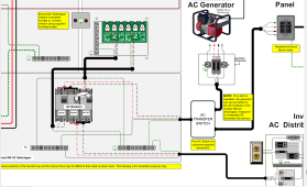
Here is a blow-up of the 4048 wiring diagram. Neutral is the grey wire. ACout is on the left, while ACin is on the right. You can see in the diagram (yeah, it's awful) That the ACout neutral is not bonded to the ACin neutral.
1640913535996.png


To answer question #2, for my own installation I utilized Midnight breakers for all aspects. The only Schneider breakers used were the ones originally imbedded in the AC and DC boxes when I bought them.
2) I understand there are differences between AC and DC breakers and they are not interchange, I’m specifically talking about the AC-Out Sub Panel circuits. It sounds like I do not specifically have to use the Schneider QOU series breakers, compatible with AC and DC, in this sub panel. This will save quite a bit of money, just wasn’t sure about this but it makes sense this way. I will be using the Schneider combo AFCI/GFCI breakers, these are very expensive either way but the QOU series are a lot more.
 
Thank you very much for the details.

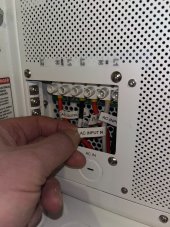
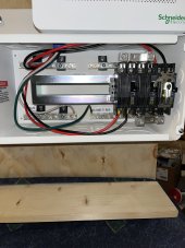
I guess what is confusing me is the Schneider AC box came with a single Neutral wire labeled ‘AC Input N’ - see attached photos.

I have this factory supplied ‘AC Input N’ wire installed in the AC-In ‘N’ terminal in the Inverter because it was labeled that way. Is this incorrect? If it doesn’t get connected to this location in the Inverter then where? Does anything get connected in the AC-In ‘N’ terminal in the inverter then?

I don’t have a Neutral wire installed in the Inv-Out N terminal yet, I haven’t made this yet but have the wire to do so. I would like to clear up the question above before I get into that.

91160AE5-CD79-4B0E-B13A-6665E3635E7C.jpegDB5E3EA9-8DFE-436B-9F62-05A9B67F7573.jpeg
 
I'm a little at a loss right now. It's been a couple of years now since I wired up my Conext, and the DC breaker box is mounted over the ACout/ACin terminals, so I can't just walk out to the workshop and take a look. Besides, it's snowing. I guess the best thing now is call back tech support and hope you get a different technician.

Going by my wiring diagram, it's the ACout that should be wired. My boxes came without premade wiring, so I did all the connections myself. I think that wire should be there for a non-bonded generator. Was no ACout neutral wire included?
 
There was definitely no ‘AC Output N’ wire included with the system, this is what has me stumped and confused.

My original question was when I make and install this missing ‘AC Output N’ wire, do I connect it to the same Neutral Bus bar that the ‘AC Input N’ wire is connected to by Schneider in the AC box I purchased? This is making less sense to me and now I’m really confused, and I called Schneider support and they told me to connect both Inverter AC Input and Output N wires to common N Bus bar but wiring diagram doesn’t show that?
 
When I originally installed my Conext, I ran a jumper wire from the neutral buss to the ground buss shown in the Conext SW AC breaker panel of your second picture above. I then ran a wire from the ACout neutral down into my Conext SW AC breaker panel to connect to make the neutral to ground connection.

Here is the Conext installation guide as an attached file.

What I would suggest you do at this point is to email tech support instead of talking over the phone and cut and paste the same area of the wiring diagram that I displayed above, where it shows the ACout neutral being bonded.

At this point, this is treading into the legal liability area, so I would rather you follow Schneider's specific recommendation, then just following what I did.
 

Attachments

  • Conext_SW_Series_Installation_Guide.pdf
    12.3 MB · Views: 28
Thanks for all your input Michael, this has been very helpful. I have a good handle on the Output details now. I will be introducing the Neutral-Ground bond at the AC In receptacle I’m adding via a dummy plug that will always be connected unless the Charger is plugged in to grid so I won’t connect this in the AC box or sub-panel I’m adding. Per all the feedback I have received this should work fine.

I’m going to be using only L1 for the Charging Circuit as it is much easier to find a 120V receptacle for the Charger as it will be moving around between job sites etc. I’m still unsure about how to handle the AC In Neutral wiring, and whether to connect this to the same neutral Bus as the AC Out. I could easily run AC In N directly from Inverter to the AC In receptacle, but not sure if I’m missing some reason that it needs to be connected to same Bus. This could damage the system so I need to be 100% sure how to do this, I’m going to contact Schneider to find out.

I’ll let you know what they say?
 
Here is a blow-up of the 4048 wiring diagram. Neutral is the grey wire. ACout is on the left, while ACin is on the right. You can see in the diagram (yeah, it's awful) That the ACout neutral is not bonded to the ACin neutral.
View attachment 77707

Maybe I'm looking at this diagram wrong, but it looks to me like AC in is the top right and AC out is bottom right.

Both have a grey neutral wire connected directly to the N bus bar.

The single N wire from the AC distribution panel/breaker box is how my XW was shipped.
The internal transfer switches don't break the Neutral, so the inverter just needs a single Neutral connection.
Again, that's the XW series, the SW may be different.
 
I just looked at that Conext manual for the Inverter that Micheal K posted and the inverter itself does have seperate L1, L2, and N wires for in and out <DELETED BAD INFORMATION> My bad, my eyesight is not what it used to be

Normally these inverter/chargers use the same transformer for the inverter and the charger. My Magnasine 4024 is wired exactly the same way. It does have seperate N(in) and N (out)

Probably due to the fact that most terminals are rated for one wire only , to connect 2 wires to one terminal you need a terminal rated for 2 wires

I think the separate input and output blocks in the inverter is a convience for those folks that do not use the breaker box, but use 3 conductor cords run to separate panels.

Sure way to know, connect an ohmmeter between the two neutral terminals.

You would need only one wire from N in the inverter to N buss bar, but two will not damage anything.


I almost bought that same inverter, then stumbled into my Magnasine MS4024AE for $500 , a deal that I could not pass up

Go look at figure 3-2 on page 3-6 very clearly shows that connection


Happy new year and lots of luck with that project.
 
Last edited:
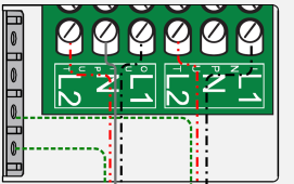
This is what I see when I blow up the wiring diagram to 600%. There is no neutral wire on the ACin neutral, only the ACout neutral. ACout is on the left and ACin is on the right. The grounding bussbar is the grey vertical bar on the far left. BTW, figure 3-2 is actually on page 3-4, but this portion is the same on both diagrams.

There are only three neutral wires coming off the neutral bussbar. The far left wire goes to the ACout neutral, the middle wire goes to the Inverter AC Distribution Panel, and the far right wire goes to the AC Transfer Switch.
1641001255179.png
 
Micheal you are so right, I was looking at the ground buss....I posted bad data...thanks for flagging that.

I will correct my post,

Still under the NEC neutrals of ”seperately derived systems” do need to have the neutrals connected togather. It maintains a common neutral point.
 
I tried many ways to copy the internal transformer wiring to show that the internals are one transformer used both for charger input and inverter output but alas you cannot copy from Adobe Books or Apple Books, Do not know why.

Its the same as the SW4024, a lot of the same people in NW Washington State have worked for both companies,
Their roots all come from Trace, That includes Midnight, Outback, Magnasine and Schneider
 
I was looking at the Yellow tabs at each connection. I'm not smart enough to know what those are
I saw that and wondered if those were crimp on terminals but looking closer I think that is heat shrink
 
Mister M1

Look real close at the red wire on the breaker, looks more like a crimp on terminal, that would be a no-no
 
Another peek reveals AWM 10 GA on the black wire, undersized,

10 ga. 30 amps intermittent......24 amps continuous

I do believe that a inverter should be considered a “continuous device”
 
Back
Top