It is certainly not the most elegant code, and I do want to go through and clean it up and comment it better. There is an initialize block that sets up a bunch of things. It creates a virtual com port #4 which is actually Modbus over TCP IP to talk to my Schneider equipment. That base com port is pointed at the IP address of the Schneider Gateway box. Then the device id tells it which device on the Schneider Xanbus it will talk to. The default device id for the first XW-Pro inverter is "10". This is the routine for reading the data I need from the XW-Pro.
' Read grid watts
DM[9] = &H66
READMB2 4,10,DM[9],DM[10],2
G = DM[11]
SETHIGH16 G,DM[10]
DM[13] = G
' Read Battery Watts
DM[9] = &H54
READMB2 4,10,DM[9],DM[10],2
B = DM[11]
SETHIGH16 B,DM[10]
DM[14] = B
' Read output watts
DM[9] = &H9A
READMB2 4,10,DM[9],DM[10],2
O = DM[11]
SETHIGH16 O,DM[10]
DM[15] = O
SETLCD 3,1," Grid Batt Out "
H$ = STR$(G)+" "+STR$(B)+" "+STR$(O)+" "
SETLCD 4,1,"W "+H$
' Read AC input voltage
DM[9] = &H62
READMB2 4,10,DM[9],DM[10],2
Y = DM[11]
SETHIGH16 Y,DM[10]
' Read Battery Current
DM[9] = &H52
READMB2 4,10,DM[9],DM[10],2
T = DM[11]
SETHIGH16 T,DM[10]
I know this code is a bit messy, but at least it has a few comments in it.
I set DM[9] to the address I want to read from the XW-Pro. It has hundreds of registers, not just 10 like in the PZEM meters. So the frist read is the "Grid Watts" on the AC1 port of the XW-Pro. The read looks just like the serial read because of the virtual com port. It does not care that it is getting the data over ethernet or serial.
READMB2 4,10,DM[9],DM[10],2
It reads from COM4, device id "10" from register stored in DM[9], puts the data in DM[10], but it is two 16 bit registers again, so the high byte is then in DM[11] as well. " ,2 " told it to read the 2 registers.
I then use the same functions to put the total 32 bit value of grid watts into the 32 bit variable "G".
Repeat this for the battery watts, and the output watts.
The end of this routine displays the data on a virtual LCD screen. The larger PLC's from Triangle Research have a 4 line x 20 character display on them, the little Nano 10 does not have it, but it thinks it does. And the PC monitoring software shows this screen. So I can watch it show the live data on that screen on my PC as it is running. That is all the "SETLCD" commands. Later I also tacked on reading the battery current and grid voltage at the end of this routine. I do need to clean up this code and make it a little nicer to read.
As the sequencer steps along, it reads all the data into the variable, then decides if it should be charging or exporting, based on the power readings and the time of day from the real time clock. Then it calculates the values and sends the commands to the XW-Pro to set the charge mode and power, or the export current amount. And it just keeps looping every 5 seconds.
400bird's Raspberry Pi solution is a lot more polished and does much more than my simple PLC arrangement. The two function blocks I showed here are ReadPZEM and GetWatts. The rest of my function blocks are
Initialize, Event Count, Clear LCD ,Connect TCP, ReadC4, Close_conn, GetTime, GetBvolts, GetCrgCurr, SetCrgCurrent, ForcBulkCharge, ChargeNoFloat, Start_Charge, SetSell
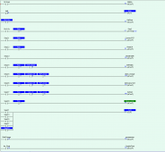
I wrote this code as I was learning how to use the Nano-10 PLC and Modbus, so my code is pretty rough, and get's better as I added new functions. At some point I want to write it from scratch, but it is working so good, I hate taking it offline. Here is a screen grab of the ladder logic part as it is running right now.
View attachment 118450
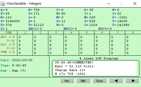
The blue highlighted is logic true contacts and energized coils, the green is the current function being run. It steps along pretty quick at 0.5 second clock, but that is actually really slow for the PLC. Here is the small live monitor screen.
View attachment 118451
That is the variable page and the fake virtual LCD screen. Click the arrows at the bottom and it has more pages where you can even see all the DM values in real time. It even has a web server, and you can look at most of the data by looking at the web page. I have not coded HTML, but evidently you can create a custom web page and load it in the memory to create a custom web service GUI. I'm not that good at coding.
If you want to go this route, I will share my code, but it is not elegant or easy to follow. And it would need to be modified to fit your system. For example, I just have the ip addresses just hard coded in, and use fixed ip on my network, so DHCP can't mess it up. My PLC is at x.x.x.5 and the Gateway is at x.x.x.144 And the power meters come set to device id 1 and you have to use their software and a usb to RS-485 adapter to get into them and set their id's to different values to have more than one connected.
Looking at this probably makes most people want to run away. If you want to dig deeper, you can actually download a student version of the Tri PLC software and it can simulate code on your PC. To get the full programming code you either have to buy a PLC or pay for a code license. The Nano-10 was about $250 USD with the real time clock module. But that was almost 2 years ago now. With the purchase of the PLC, you get a full version of the programming environment. It actually runs in Java. Once the PLC is programmed, it runs on it's own and the PC does not need to do anything, I only look in on it from time to time now that it is pretty stable. It has crashed on me twice, but I traced that to an odd divide by zero which I finally found and then added code so it will use a fixed value if it reads a zero that the comm error routine does not catch.


") ).
).