diy solar

diy solar

Segregated Battery Post on Battery

Inq720

Odysseus, expert on the Siren's call
Joined
Nov 25, 2020
Messages
142
Location
North Carolina Mountains
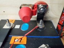
I've received my (4) Lishen 272 Ah cells and have started my first Top Balance. Normally, I know one typically has a single positive post and a single negative post. I have a limited volume for mounting my system in a boat, but will have ready access to the top of the battery. Consider, that it seems reasonable that I'll have three main connections:
  1. 150 amp Inverter.
  2. 60 amp lead going to a fuse block for small load items.
  3. 20 amp lead coming from the charge controller.
Normally, someone would connect a large wire from the positive post to a bus and then segregate out these three main leads. I'd like to suggest building these directly into the battery. The drawing below shows the last two cells of the battery with the standard bus bars. I would then cut down a bus bar and drill two extra holes in it. This would act as the positive distribution bus. I would use Mini ANL fuses. The largest current item (150 amp Inverter) would be connected directly to the positive cell post using the grub screw and serrated nut. This would clamp the fuse directly to the modified bus bar, clamping to the top of the positive cell post. The next largest load (60 amp lead to fuse block) would be connected to the modified bus bar next and the lowest would be connected next to it. I plan to 3D print an ABS cover for the (4) cells with partitions between these fuses to keep everything nice and tidy. The advantages I see for this design are:
  1. No remote positive bus that I'd have to put is some remote / obscure place with limited access. I'd have ready access to the top of the battery with the three fuses.
  2. Reduce part count, no main wire to remote block, no remote block, no mounting hardware, no lugs... etc. IOW, less to corrode and cause issue long-term.
  3. Direct connection of the loads to the positive post. The largest load right at the cell post.
  4. Once in the case with custom ABS printed top, the only exposed posts would be negative and the fused ends. The fuse side connected to the modified bus bar will be under plastic. Thus an accidental short (dropped tool) would be across the single negative post and the end of a fuse... thus blowing the fuse... not the tool.
Can you think of any pitfalls to this design I should consider???

Thank you for your help.
1613213371165.png
 
I’ve done something similar with my 48v build. I’m also using Lishen 272Ah cells. I bent a section of 3/4”x1/8” copper bar stock for the main Pos connection and drilled holes for two 100A breakers (one for each 3000w inverter). I also included an extra small hole on my main Neg bar to accept accessory connections. Pic below. Full build thread for my pack is here: LINK. Haven’t had anyone comment on this specific aspect of my design, but it seems to be working fine.

94EFB535-4A72-480D-9A18-E4D6CF0238BF.jpeg
 
Bar would need to be thick enough to thread bolts to. Or mounted high enough to allow nuts under them, but it is done all the time.
Good point. If you’re using copper, I would definitely go with Nuts, or something like a carriage bolt mounted from below (to create a stud on top). If you’ve got a vice, or even just some decent clamps, should be pretty easy to put two bends in the bar to raise the fused part up.
 
Last edited:
Good point. If you’re using copper, I would definitely go with Nuts. If you’ve got a vice, or even just some decent clamps, should be pretty easy to put two bends in the bar to raise the fused part up.
I have bussbars threaded with studs in them and nutknobs for cabling...
 
Geeze guys! Thanks. For some reason, I didn't get my usual email notification and I was feeling kind of lonely. Logged on and bam... 7 hits already. I was expecting all kinds of doom and gloom... with you all actually using something like this and that BlueSea has an actual product, is encouraging.

Looks like there is about a 6.5 mm gap between the bar and top of the battery. I was going to tap the holes in the bar, and use a hex head bolt from below hoping it would stay tight enough to use as a post. As a backup if the bars are nickel plated copper and won't handle torqueing the fuses down, I'd have to add a nut on top between the bar and fuse.

I think I would slide the bus bar to the right 1 hole so it wasnt such a cantilever.

Hadn't even thought of that one... but great idea and plenty of room and more clearance to the negative post! Might use the same concept on the negative post and have all three negative connections arranged similarly.
 
Can you think of any pitfalls to this design I should consider???
A few.
The stresses on the battery terminal will be high.
The ANL fuse has little mechanical strength and relies on a substantial fuse holder to support cable connections and associated stresses.
ANL fuse has an interrupt capacity of 2700 amps (LittleFuse)(Bussmann).
Since the the short citcuit current of a 270Ah 12v battery may be in in the region of several thousand amps amps, perhaps a MRBF fuse ( BlueSea)(Bussmann), that has a interrupt rating of 10000 amps at 14 volts, would offer better protection. A search on the forum will suggested that a class T fuse would be the ideal solution.
Since this is going to be installed in a boat, a degree of flexibility in the connections from the main terminal studs to the fuse array would seem to offer advantages. One high current master fuse, perhaps a MRBF fuse or class T, near to the battery post, then a cable to a distribution fuse block would be a solution.

Mike

Mechanical - I agree completely, that I don't want to mechanically stress the post. I was actually taking that into account with the Mini ANL fuses. Any torque/bending imparted by the massive Inverter cables would just snap the fuse. I'd have to make sure they are well tied down leading to the fuse. Guess... the fuse acts as a electrical and structural fuse. :)

Electrical - Just started trying to find something that explains "interrupt capacity" to me in layman terms. I searched this forum and get plenty of hits... but no definitions so far. Internet search - same thing. If a fuse is rated at 150 amps... surely 10,000 amps is going to pop it just as well as 170 amps. So, I'm just not getting it. Could someone point me to a reference.
 
the air has finite resistance and if a fuse isn’t designed for the interrupt capacity then a sustained arc could happen

fuse blows, no more metal

battery doesn’t care, starts conducting through the air

air: is plasma

battery: has bad day, ow
 
interrupt capacity in amps: if the short circuit causes more than this number of amps to flow, it might not successfully disconnect, which is the main purpose of a fuse
 
Mechanical - I agree completely, that I don't want to mechanically stress the post. I was actually taking that into account with the Mini ANL fuses. Any torque/bending imparted by the massive Inverter cables would just snap the fuse. I'd have to make sure they are well tied down leading to the fuse. Guess... the fuse acts as a electrical and structural fuse. :)

Electrical - Just started trying to find something that explains "interrupt capacity" to me in layman terms. I searched this forum and get plenty of hits... but no definitions so far. Internet search - same thing. If a fuse is rated at 150 amps... surely 10,000 amps is going to pop it just as well as 170 amps. So, I'm just not getting it. Could someone point me to a reference.
Interrupt capacity is to show how much a short circuit massive amperage the fuse is rated for.
In other words, if the batteries are CAPABLE of a 15,000A delivery in the event of a short, using a fuse that is only rated to interrupt 5000 or 10,000 amps there will be a fault possibility that the fuse will not protect from.

the rated amps is for normal overload. So a 170A fuse can carry up to 170A of normal load, but if there is a damaged equipment fault that gives a direct short circuit, the battery WILL draw more than 5000A if the battery is capable of it.
 
Please understand, I'm not arguing... just trying to get a handle on this issue. Based on the premise so far, lead-acid (even AGM) just aren't strong enough to be an issue and thus the car Audio hard-core are fine with the ANL fuses. As soon as you go to Lithium, it makes it sound like EVERY short could pump 10kA and thus require this class T type fuse.

Trying to look at it from a non-EE viewpoint, I can easily visualize a circuit breaker welding shut due to high current before the mechanism has a chance to open and thus needing a class T device. I've always been under the impression arcing is a high voltage issue... static electricity, florescent lights, neon light... etc are high voltage, and low amperage and naturally arc. I plugged the question "high amperage arcing" in Google... and got this hit with just as much argument on both sides.

So I'm not the only one confused.
 
Please understand, I'm not arguing... just trying to get a handle on this issue.

Try to think of it like electron inertia. Once it starts, the gap that is created by an ANL fuse isnt enough and the electrons may/can jump the gap. A T class fuse opens a large enough gap that the electrons cant jump and it.
 
Try to think of it like electron inertia. Once it starts, the gap that is created by an ANL fuse isnt enough and the electrons may/can jump the gap. A T class fuse opens a large enough gap that the electrons cant jump and it.
Got it! :ROFLMAO: Us AE/ME types can wrap our head around inertia. The Wikipedia article on "Breaking Capacity" was pretty thin, but added one tid-bit to my understanding - DC is worse than AC since AC at-least passes through zero volts occasionally. Perfectly logical. Can anyone recommend articles with a little more meat of the "mechanics of the phenomenon" than this one?

I'm gathering the suggested plan is to have a class-T as a "master" breaker before parsing out to smaller fuses/breakers for individual devices???

I know I'm sounding thick... but one more time... in the circuit: LFP battery -- 120A BMS -- 150A fuse -- SHORT?
  1. If its a non-class-T fuse, the inertia keeps the circuit alive. The next thing that gets destroyed is the BMS. Does its destruction, break the connection and save the house/car/boat/etc? Just the physical dimensions of the BMS seems to suggest that gaps are large enough that inertia-arcs would not be maintained.
  2. If its a class-T fuse, it safely opens the circuit. Besides saving the house/car/boat/etc, does it also protect the BMS?
 
Last edited:
(Continued)
If Inertia is an accurate corollary, then current (100kA available in the battery) can't accelerate up beyond what the BMS supplies (120 amps) to reach the short. So we never reach even the 150A fuse limit (class-T or not).
  1. For the scenario of needing a class-T, does this imply a double-failure: The short say in the Inverter AND the BMS fails at its short-circuit protection?
  2. Does this mean I should place the class-T between the negative LFP terminal and the leads going to the BMS?
 
I think I would slide the bus bar to the right 1 hole so it wasnt such a cantilever.
That is a concern others have expressed about the ability of the terminal top to take stress, especially in a mobile environment.
Here is what I have done but it does not accomodate three fuses. This is a portable pack and the plywood is part of the compression mechanism. In your case, I would use a braided device because of vibration.
EDIT: I just discovered this is an old thread. This may be too late for OP but useful for subsequent readers.
 

Attachments

  • 20200925_172520.jpg
    20200925_172520.jpg
    64.6 KB · Views: 12
Back
Top