diy solar

diy solar

Semi-DIY BMS: Active Balancer + Microcontroller

Yes but you can't ignore the 100 k resistor, the error you can get is higher than what you calculated. Also the 6 M figure is a typical value, worst case can be worse. And the leakage current is random within the range specified, it's not like it's a nice fixed 6 M resistor, so you can't really calibrate it.

Often you'll find the recommended maximum value for input resistors in the datasheet section talking about the anti-aliasing filter (but also apply to any other resistance like your voltage divider for example). Here it says "Limit the filter resistor values to below 1 kΩ." and I would highly recommend to follow that, but that means your voltage divider will have a very low impedance so a high current consumption. That's why you want to use an op-amp so you can have a high impedance divider ;)
Clearly I need to read (and understand) these spec sheets better. In this case of my voltage divider, is the 'filter resistor' R1? If that's the case, current consumption would be insane. Op-amp it is. I'll need to do some homework on this, including reviewing the parts you and Cal are using, to figure out what I need and how to use it. I won't ask you for a recommendation (although I would accept one...), but any links to documentation that might steer me in the right direction would be much appreciated.
Also, the Vdd + 0.3 V figure is from the absolute maximum ratings table, never design using those values (read the warning just under the table for more info). The recommended operating conditions table says Vdd is the max for input voltage (and personally I would avoid going near Vdd anyways since you can expect having most of the non-linearities here).
Good point. I was thinking of it as a absolute max, but the possible upper end of my pack voltage range does put me above Vdd (58.4v / 11 = 5.31V). Will definitely plan to target voltages below 4.5 in the final design.
Note: the datasheet says "If a VDD supply voltage greater than 4 V is used, the ±6.144V full-scale range allows input voltages to extend up to the supply. Although in this case (or whenever the supply voltage is less than the full-scale range; for example, VDD = 3.3 V and full-scale range = ±4.096V), a full-scale ADC output code cannot be obtained. For example, with VDD = 3.3 V and FSR = ±4.096V, only signals up to VIN = ±3.3 V can be measured. The code range that represents voltages |VIN| > 3.3 V is not used in this case." so if you power the ADC with 5 V the recommended configuration would be to use the 4.096 V reference and scale your input signal to be just under that.
When defining the range of the ADS1115, I was mainly focused on the current sensor, which has a range of 2.5 +/- 2.5V. To avoid having to divide the current sensor voltage (or limit its range), I was planning to use the full range of the ADS. I realize that I'll probably sacrifice a bit of linearity at the very top end of the sensor's limit, but I really don't expect to be pulling 150A very often. I may end up moving to a current sensor with a 3.3v operating range anyway, which would allow me to go with the +/- 4.096V range without dividing.
Note²: the datasheet also says "Single-ended configurations use only one-half of the full-scale input voltage range." so in SE configuration it's like you have a 15 bits ADC at best. It's not a big deal but you can't ignore it in your accuracy and resolution calculations.
Yes, that's right. I'm only getting 15-bit resolution the way I'm using it. That seems to be the case even for my differential measurements (i'm using the Vref from the current sensor for differential measurements).

Thanks so much for all the info BidulOhm. I'd be nowhere on this without the info guys like you have generously shared on this forum.

-jon
 
Clearly I need to read (and understand) these spec sheets better.

Well, ADC datasheets aren't the simplest to understand sometimes. Datasheet reading also require some prerequisite knowledge, mainly about the terms used.


In this case of my voltage divider, is the 'filter resistor' R1?

It's a bit more complicated than that but bascially your resistor in this case would be the the 10 k one. But putting 1 k and so having the other one around 15 k means around 4 mA and around 1/4 W of dissipated power which means you would need to go to a 1/2 W or more resistor which is not ideal given the other constraints, and even without going here, 4 mA just for a voltage divider is super high and not really good practice.


Op-amp it is. I'll need to do some homework on this, including reviewing the parts you and Cal are using, to figure out what I need and how to use it. I won't ask you for a recommendation (although I would accept one...), but any links to documentation that might steer me in the right direction would be much appreciated.

Well, you can read the topic on the design of my BMS (the complete one, not the summary) but it's pretty long even if you skip what you don't care about.

Basically if a few $ for just one op-amp isn't a problem for you then I recommend the OPAx189 (that's actually the one I use for this application and the current shunt amplifier too, U150 on the attached schematic), and if you prefer something cheaper but with less good specs (still a wonderful op-amp) there's the OPAx991 (even cheaper is the OPAx990 but the 991 has far better specs for only a small price difference) ;)

Fortunately here you just need a very simple voltage follower (BTW this page should be useful if you're starting with op-amps) which is the simplest topology possible so you should have no problem implementing that.

For more info on op-amps I recommend this website (don't forget to go see the other pages listed at the end of this one), you can ignore the equations at first and focus on understanding how it works for now ;)


When defining the range of the ADS1115, I was mainly focused on the current sensor, which has a range of 2.5 +/- 2.5V. To avoid having to divide the current sensor voltage (or limit its range), I was planning to use the full range of the ADS. I realize that I'll probably sacrifice a bit of linearity at the very top end of the sensor's limit, but I really don't expect to be pulling 150A very often. I may end up moving to a current sensor with a 3.3v operating range anyway, which would allow me to go with the +/- 4.096V range without dividing.

Yes, that's right. I'm only getting 15-bit resolution the way I'm using it. That seems to be the case even for my differential measurements (i'm using the Vref from the current sensor for differential measurements).

I see. But according to the datasheet of the sensor the ouput is +/- 1.15 V relative to Vref. So you would use the ADC in differential mode connecting the Vref to the -Vin of the ADC. And so you can configure the ADC to use the 1.024 V ref when doing the current measurement (yes, you wouldn't be able to go right to the max of the sensor by doing that) and the 4.096 V one when doing the voltage measurement. Or just scale the voltage to use the 1.024 V ref all the time if you prefer (but that would introduce more errors so better use the first solution).


Thanks so much for all the info BidulOhm. I'd be nowhere on this without the info guys like you have generously shared on this forum.

Thanks; you're part of sharing too ;)
 

Attachments

  • BO_BMSB_16.pdf
    291 KB · Views: 18
Last edited:
Op-amps are the swiss army knife of analog circuit design. There are many variations, but building a follower circuit is simple and reliable.

You can set up basic DC circuits in one of the free versions of the SPICE simulator, and play around with different values. In this case voltage divider circuits are only accurate when the input impedance is very high and stable. When you are trying to measure within 0.1% accuracy, going with an amplified solution is best.

I feel your pain though. I am an Mechanical Engineer (at least that is what my diploma says). But I keep running into projects where analog and embedded circuits are the only way to solve a problem. There is a tremendous amount of background knowledge needed for some of this stuff. It does help to have someone who can point you in the right direction.
 
Well, you can read the topic on the design of my BMS (the complete one, not the summary) but it's pretty long even if you skip what you don't care about.

Basically if a few $ for just one op-amp isn't a problem for you then I recommend the OPA189 (that's actually the one I use for this application and the current shunt amplifier too, U150 on the attached schematic), and if you prefer something cheaper but with less good specs (still a wonderful op-amp) there's the OPA991 (even cheaper is the OPA990 but the 991 has far better specs for only a small price difference) ;)

Fortunately here you just need a very simple voltage follower (BTW this page should be useful if you're starting with op-amps) which is the simplest topology possible so you should have no problem implementing that.

For more info on op-amps I recommend this website (don't forget to go see the other pages listed at the end of this one), you can ignore the equations at first and focus on understanding how it works for now ;)
THANK YOU!
I see. But according to the datasheet of the sensor the ouput is +/- 1.15 V relative to Vref. So you would use the ADC in differential mode connecting the Vref to the -Vin of the ADC. And so you can configure the ADC to use the 1.024 V ref when doing the current measurement (yes, you wouldn't be able to go right to the max of the sensor by doing that) and the 4.096 V one when doing the voltage measurement. Or just scale the voltage to use the 1.024 V ref all the time if you prefer (but that would introduce more errors so better use the first solution).
First, I should have highlighted the fact that I'm not currently using the sensor listed at the top of this thread (the HOYS 100-S/SP33), which I haven't been able to find in stock. That sensor operates at 3.3V, with sensor output at +/- 1.15V. I'm currently using a HASS 50/S, which operates at 5V and has a range of +/- 2.5V.

That said, what you're suggesting (connect the sensor's V-ref to V-in, rather than to one of the analog inputs) makes a ton of sense. I've got a HOYS-200-S/SP33 (500A range) here in the lab (ie, pingpong table in the basement cluttered with random components) that i was thinking wouldn't be sensitive enough, but it may be in this configuration. I'll need a separate ADS for the voltage measurement (right?), but just happen have order more last week. This configuration also allows me to speed up the sampling rate of the ADS, as it won't have to measure two different inputs to get the differential measurement (trying to catch as many points on the ripple as I can).

Thanks again!
 
Op-amps are the swiss army knife of analog circuit design. There are many variations, but building a follower circuit is simple and reliable.

You can set up basic DC circuits in one of the free versions of the SPICE simulator, and play around with different values. In this case voltage divider circuits are only accurate when the input impedance is very high and stable. When you are trying to measure within 0.1% accuracy, going with an amplified solution is best.

I feel your pain though. I am an Mechanical Engineer (at least that is what my diploma says). But I keep running into projects where analog and embedded circuits are the only way to solve a problem. There is a tremendous amount of background knowledge needed for some of this stuff. It does help to have someone who can point you in the right direction.
Mechanical Engineer...you're miles ahead of me (Analytical Chemist). I had never heard of an Arduino, much less an Op-Amp, before I started this battery build project.

I actually downloaded LTSpice a few days ago with the assumption that i was going to need it for this project. Now I have to figure out how to use it...
 
First, I should have highlighted the fact that I'm not currently using the sensor listed at the top of this thread (the HOYS 100-S/SP33), which I haven't been able to find in stock. That sensor operates at 3.3V, with sensor output at +/- 1.15V. I'm currently using a HASS 50/S, which operates at 5V and has a range of +/- 2.5V.

Oh ok, this explains that then ^^


hat said, what you're suggesting (connect the sensor's V-ref to V-in, rather than to one of the analog inputs) makes a ton of sense.

Not sure what you're talking about but I was talking about connecting the sensor Vref to the ADC negative analog input.


I'll need a separate ADS for the voltage measurement (right?)

No, it has an integrated MUX so you don't need multiple ADC or an external MUX ;)


This configuration also allows me to speed up the sampling rate of the ADS, as it won't have to measure two different inputs to get the differential measurement (trying to catch as many points on the ripple as I can).

No, when using an ADC in a differential mode you only need to do one sampling per measurement, same as in single ended mode. Basically differential means that your measurement ground isn't the system ground anymore but the negative input instead (I know, it's somewhat inexact but I'm simplifying a lot, so...), that's all. It's mainly used to avoid noise and offset coming from the system ground.

Also, you don't really need much speed for this application, a few dozens S/s is plenty enough, so that's not a problem.
 
Just to muddy the waters a bit, TI has a couple BMS chips which are designed specifically to measure a battery packs voltages, and report them over a digital bus. They also have an output which can drive a balance resistor. Most are plus mins 3mV accuracy. There are some up to 16S, though you could chain two 8S units with a common bus. If I recall correctly, some also natively support a current measurement shunt, which would help keep the component count down.

A basic BMS implementation would consist of the BMS chip and a few companion components, bus isolation (if required by the application), balance resistor/FET array, and an embedded controller which commands the BMS core chip and handles logic/comm.

The only major annoyance with this approach is that you need to make custom circuit, and sourcing some of these components in a non surface mount form factor may not be possible. There are reference designs which come on a board, and those may work with a bit of hacking. Otherwise a custom PCB with surface mount components is not easy DIY.
 
Last edited:
Not sure what you're talking about but I was talking about connecting the sensor Vref to the ADC negative analog input.
At present, I've got the Vref from the sensor connected to the A0 input, and the Vout (signal) connected to the A1 input. I'm using the function "ads.readADC_Differential_0_1( )" to read the sensor data. When you said "you would use the ADC in differential mode connecting the Vref to the -Vin of the ADC", were you suggesting something different from what I'm doing? Do I need to set A0 as "-Vin" in my code somehow? And with it set up how I have it, am I constrained to the Vmax of the signal line (2.5V + 2.5V = 5V), or the max difference (Va0 + Va1 = 2.5V) when determining my gain setting?

No, it has an integrated MUX so you don't need multiple ADC or an external MUX ;)
But I can't use two different gain settings when muliplexing, can I? I thought that's what you were suggesting.
No, when using an ADC in a differential mode you only need to do one sampling per measurement, same as in single ended mode. Basically differential means that your measurement ground isn't the system ground anymore but the negative input instead (I know, it's somewhat inexact but I'm simplifying a lot, so...), that's all. It's mainly used to avoid noise and offset coming from the system ground.
Got it.
Also, you don't really need much speed for this application, a few dozens S/s is plenty enough, so that's not a problem.
Yeah, I was finding that I need to average about 25 samples to smooth out the ripple. Even better at 50. With the default conversion delay (9ms), it takes about 500ms to collect those 50 samples. I suppose that's only a problem if I want to log/use the data at a frequency higher than 1 measurement/sec, which I don't think I need to do.
 
At present, I've got the Vref from the sensor connected to the A0 input, and the Vout (signal) connected to the A1 input. I'm using the function "ads.readADC_Differential_0_1( )" to read the sensor data.

That's correct ;)


When you said "you would use the ADC in differential mode connecting the Vref to the -Vin of the ADC", were you suggesting something different from what I'm doing? Do I need to set A0 as "-Vin" in my code somehow?

Oh I see, it's the term -Vin who is a problem. -Vin is a generic name for a negative input in a differential system (same for op-amps btw) and it's A0 in your case (although I wonder if in the ADC the negative input isn't actually A1; oh well, it doesn't matter much in your case anyways).


And with it set up how I have it, am I constrained to the Vmax of the signal line (2.5V + 2.5V = 5V), or the max difference (Va0 + Va1 = 2.5V) when determining my gain setting?

The sensor output evolves between 0 and 5 V. The sensor Vref is 2.5 V. So the output will be between -2.5 and +2.5V relative to the sensor Vref.

The ADC inputs can go from 0 to Vdd (5 V in your case) but you can only sample them between 0 and the Vref selected in the ADC (for example 4.096 V). So while (A1 - A0) can go from -4.096 V to +4.096 V both must remain between 0 and 4.096 V to have a valid result.

In your case the sensor doesn't have a true differential output, it's in fact a single ended output (0 - 5 V) with a Vref equal to half the FS output (2.5 V).

What that means is that you'll lose the ability to sample what's between 4.096 and 5 V so from the sensor point of view you'll only be able to measure -2.5 V to around +1.6 V so for a 100 A sensor that would mean -100 A to +64 A for example (you can swap the signs if you swap the connections to A0 and A1 BTW).

Now, in theory you can use the 6.144 V ref and sample up to 5 V but personally I wouldn't do that because of lower accuracy near the voltage rail and because you'll lose some resolution as what's between 5 and 6.144 V is lost. I'd rather scale down the sensor voltage (and the sensor Vref too of course, differential = what you do on one side you do on the other too, else you'll have problems).


But I can't use two different gain settings when muliplexing, can I? I thought that's what you were suggesting.

I didn't read the datasheet in details on that part but I'm 99 % sure it's not a problem since you can configure the internal Vref with software, as well as the MUX. The MUX is just a bunch of switches to select which inputs you sample, that's all (actually look at the internal block diagrams in the datasheet, you'll see they litteraly draw switches in them) so it shouldn't interfere with the rest.


Yeah, I was finding that I need to average about 25 samples to smooth out the ripple. Even better at 50. With the default conversion delay (9ms), it takes about 500ms to collect those 50 samples. I suppose that's only a problem if I want to log/use the data at a frequency higher than 1 measurement/sec, which I don't think I need to do.

In theory that would be best taken care of with an analog filter before the ADC because if you do it in software you might have some problems you can't solve, aliasing being the main one. In theory, since you want an average in the end, you can cancel aliasing by adding a long enough random delay between your measurements and average enough of them, but it's not ideal and a simple RC filter in front of the ADC would be a lot better.

Also, note that for a given ADC the faster you sample the less accurate your sample gets. You need to do some calculations to see if it's better to sample fast and average a lot of them, or sample slower and so average less of them. Also note that for averaging samples to work you need enough random noise on the input (which shouldn't be a problem in our application) and that ROI gets pretty low pretty quickly (averaging more than a few dozens samples isn't worth it usually) but of course that depends on what you want, what you do, how you do it, etc... Also, averaging only gets you more ENOB, it doesn't fix errors like thermal drift, etc...
 
In theory [noise] would be best taken care of with an analog filter before the ADC because if you do it in software you might have some problems you can't solve, aliasing being the main one.
Yeah, I've definitely seen aliasing with some sampling frequencies, and i agree that analog filtering seems like a better solution than what I'm doing. So, in addition to your posts on Op Amps, I'll be reading the ones on low pass filter design!
 
Just to muddy the waters a bit, TI has a couple BMS chips which are designed specifically to measure a battery packs voltages, and report them over a digital bus. They also have an output which can drive a balance resistor. Most are plus mins 3mV accuracy. There are some up to 16S, though you could chain two 8S units with a common bus. If I recall correctly, some also natively support a current measurement shunt, which would help keep the component count down.

A basic BMS implementation would consist of the BMS chip and a few companion components, bus isolation (if required by the application), balance resistor/FET array, and an embedded controller which commands the BMS core chip and handles logic/comm.

The only major annoyance with this approach is that you need to make custom circuit, and sourcing some of these components in a non surface mount form factor may not be possible. There are reference designs which come on a board, and those may work with a bit of hacking. Otherwise a custom PCB with surface mount components is not easy DIY.
I looked at some of those chips as well as the 'development boards' they offer (Yikes on the price tags). I realized pretty quickly that cell-level voltage monitoring (and balancing) was way above my skill/knowledge level. In fact, pack-level measurements clearly are as well, but that's what I have you guys for!!!
 
As I understand it, the ADS1115 has an impedance in the neighborhood of 6M ohms. I'm currently using a voltage divider w/ R1 = 100k, and R2 = 10k. With R2 @ 10k, my leakage current is 0.465 mA ((51.2V / 11) / 10k ohm), which seems ok? Again, if I'm understanding this correctly, with some current leaking through the ADS, the ADS and R2 basically become another voltage divider. So, my 'ideally' divided voltage of 4.655 becomes 4.647 [4.655 * (6M / (6M+10k))]. Which corresponds to an error of -0.116%. So, for a true value of 51.20, my reading would be 51.11.

I would convert the resistor divider into a Thevenin equivalent circuit. The 51.2V source changes to Vth = 4.65V with a source impedance of Rth = 9.09 k ohm.

Connected to the equivalent circuit is the ADS1115 6 M ohm common mode resistor, creating the voltage divider:

V = 4.65V * 6 M / (6 M + 9 k)

This result is slightly different from the OP's. The error is slightly lower (0.149% vs. 0.166%) when accounting for R1.
 
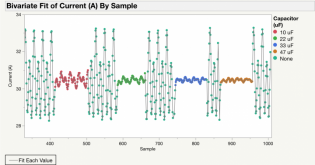
Here's a first crack at adding low pass filtering to the current sensor. Based on the guidance in the ADS1115 data sheet about max filtering resistance value (NMT 1k), I started there. I fed both the Vref and Vout signals through 1k resistors, and then tried a bunch of different capacitor value on the signal line. The plot below shows the effect of filtering on the measured values (measurement interval = 133ms, single sample per measurement here, so no 'digital' filtering). EDIT: I should add that all measurements are taken with a 30A charge coming from a Growatt inverter.

All four of the capacitor values show below have a significant effect. I believe the 10uF cap (red points) corresponds to a low-pass of 16hz, while the 47uF cap (orange points) would be 3.4hz. Not sure what I should be using as my lower limit for frequency. I imagine that I want to avoid filtering out any real/meaningful spikes in the current? So maybe 22hz / 7.2hz is a good balance?

filtering.png
 
Last edited:
Typically short circuit events will be covered by the fuse/breaker. So you just need to detect current changes on the order of 0.1-0.5 seconds. I don't see any reason not to hardware filter for minimal noise/ripple.

If you are performing coulomb counting, the hardware filtering will make your job much easier as well.
 
Another thought is to make sure you aren't creating a peak charge circuit by having too large a capacitor/resistor ratio. That would negatively effect the accuracy, by skewing it higher. I am not sure what the internal circuitry looks like on the current sensor, so it may not be an issue.

That doesn't look to be the case, but it should be trivial to compare the average of unfiltered samples to filtered ones. To confirm accuracy.
 
Typically short circuit events will be covered by the fuse/breaker. So you just need to detect current changes on the order of 0.1-0.5 seconds. I don't see any reason not to hardware filter for minimal noise/ripple.

If you are performing coulomb counting, the hardware filtering will make your job much easier as well.
Yeah, that makes sense, I suppose. So, the 47uF cap, for example, would have a 'response time' of something like 0.3 seconds. If I'm sampling once per min, that seems like it would be fine...i guess.

Anything else I should look at to make the RC filter more effective? I'm currently using cheep electrolytic caps. Would a different cap type behave differently?
Another thought is to make sure you aren't creating a peak charge circuit by having too large a capacitor. That would negatively effect the accuracy, by skewing it higher. I am not sure what the internal circuitry looks like on the current sensor, so it may not be an issue.

That doesn't look to be the case, but it should be trivial to compare the average of unfiltered samples to filtered ones. To confirm accuracy.
Once I'm done with this 30A charge, I'll take a look at how the system performs at lower current values. Make sure that the caps are not pulling it away from zero or something.
 
At the frequencies your dealing with, I don't think changing to a ceramic cap would have a noticeable impact?

If you are doing coulomb counting/integration, I think once per second is probably going to work. There aren't many loads with cycle times which are close to that frequency.

I think somewhere around 0.3-0.5 second sample rate may be desirable for some troubleshooting. Some surge/peak behavior is on that kind of timescale.
 
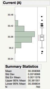
Here's a statistical look at the combined effect of the RC filter (1k ohm / 33 uF) and digital smoothing using a 25-sample average. Data collection frequency is still 133ms. 783 samples, or about 100 seconds of sampling. Standard deviation is 0.032A, or just over 0.1% of the 30A charge current. I can definitely live with that. That said, this is just short-term noise. I'm sure there will be lots of other sources of error to deal with.

1615925072968.png
 
If your objective is to just measure current and battery voltage then INA226 might be a great alternative. It contains a 16-bit adc, so current measurements are very accurate when using a shunt.


If your objective is to just measure current and battery voltage then INA226 might be a great alternative. It contains a 16-bit adc, so current measurements are very accurate when using a shunt.
Interesting. It looks like that one is only good for up to 36V. I'll poke around and see if they make something similar that can go up to 72ish.
 
Back
Top