The New JC777
New Member
- Joined
- Sep 17, 2020
- Messages
- 152
1st order 07-12-2020 4 cells EVE LF280. Total price to my door with shipping and all taxes and fees $376.00 USD
2nd order 07-13-2020 12 cells EVE LF280. Total price to my door with shipping and all taxes and fees $1128.00 USD
3rd order 09-12-2020 32 cells EVE LF280. Total price to my door with shipping and all taxes and fees $3012.00 USD (Shipping delayed)
The first 2 orders were shipped together. From date of order to tracking number was 10 days. They arrived 09-02-2020.
3 of the boxes were in good condition with (all things considered) and well packed. One box had a torn corner.
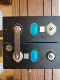
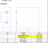
Visual inspection of the cells found 1 cell with a dent in the corner and in the middle of the cell. After a few posts on the Alibaba messaging system, Mr Dao, the owner of Senberry sent a new cell. it is in transit. He gave me the wrong tracking number. I was frustrated to say the least, but he apologized over and over. He was always checking with me to see if they had arrived.Open Circuit Voltage of the cells were all reasonable when compared to each other with only a few mv spread. The measuerments of the cells match EVEs specs. I did notice that on a few of cells that one of the wide sides is very slightly concave and the other was slightly bowed out.
Included in the purchase were stainless steel studs, nuts and nickel plated copper cell interconnects. The studs and nuts are of good quality. The cell interconnects suck, they are very thin, narrow. I will not use them.
The US dime is there for a reference and is appx. 1mm larger that the cell terminal and about 1mm thinner than the cell interconnect. Notice all of the un-used contact patch.

Top Balance charge was done with a 1s 3.65VDC CC/CV 10 amp charger. The OCV of the chrarger is 3.656 vdc. The current was measured with a clamp meter at 9.77 amps all the way through the charge. Each cell was charged independently. Some went to 3.656 in as little as 10 minuets while others took up to 76 minuets. I also noticed that once the cells reached 3.4 vdc the mv rose at about 1mv every every 15 seconds and at about 3.55vdc the mv rose at 1mv per second. It is my belief that this method of top balancing is the most accurate, but you can not leave the charger connected for long periods of time at 3.656 because LFP cells will overcharge.
Internal resistance readings are consistent @ 0.16m/ohms to 0.17m/ohms in all 16 cells after top balance charge.
About Mr. Dao. I am not affiliated with him except as a customer, however, w have conversed many many times at all hours of his night and my day. We are 12 hours apart. some of our chats got personal which I initiated so I could get to know the man I was sending thousands of dollars to half way around the world. He is full of piss and vinegar like I was at his age. He is 27 years old, his Grandmother is 75 years old,he failed English at university. When I told him my age he started calling me Sir. He is very aggressive in his business and has sold 2000 cells since August. I told him about his cell interconnects and he is looking for better ones, I am looking for him as well. I have plenty of 1" x 1/8" copper bars.
Yesterday I was shopping Alibaba to purchase other components but the shipping was ridiculous. I asked Mr Dao if he would ship them for me with the current shipment of my batteries. He said Yes so I made my purchase with the other vendor. They charged me $11.00 USD to ship the components across town to Mr. Daos facality saving me about $150.00 USD. This is what caused the delayed shipment.
Please forgive my punctuation and spelling as I failed English too!
2nd order 07-13-2020 12 cells EVE LF280. Total price to my door with shipping and all taxes and fees $1128.00 USD
3rd order 09-12-2020 32 cells EVE LF280. Total price to my door with shipping and all taxes and fees $3012.00 USD (Shipping delayed)
The first 2 orders were shipped together. From date of order to tracking number was 10 days. They arrived 09-02-2020.
3 of the boxes were in good condition with (all things considered) and well packed. One box had a torn corner.
Visual inspection of the cells found 1 cell with a dent in the corner and in the middle of the cell. After a few posts on the Alibaba messaging system, Mr Dao, the owner of Senberry sent a new cell. it is in transit. He gave me the wrong tracking number. I was frustrated to say the least, but he apologized over and over. He was always checking with me to see if they had arrived.Open Circuit Voltage of the cells were all reasonable when compared to each other with only a few mv spread. The measuerments of the cells match EVEs specs. I did notice that on a few of cells that one of the wide sides is very slightly concave and the other was slightly bowed out.
Included in the purchase were stainless steel studs, nuts and nickel plated copper cell interconnects. The studs and nuts are of good quality. The cell interconnects suck, they are very thin, narrow. I will not use them.
The US dime is there for a reference and is appx. 1mm larger that the cell terminal and about 1mm thinner than the cell interconnect. Notice all of the un-used contact patch.

Top Balance charge was done with a 1s 3.65VDC CC/CV 10 amp charger. The OCV of the chrarger is 3.656 vdc. The current was measured with a clamp meter at 9.77 amps all the way through the charge. Each cell was charged independently. Some went to 3.656 in as little as 10 minuets while others took up to 76 minuets. I also noticed that once the cells reached 3.4 vdc the mv rose at about 1mv every every 15 seconds and at about 3.55vdc the mv rose at 1mv per second. It is my belief that this method of top balancing is the most accurate, but you can not leave the charger connected for long periods of time at 3.656 because LFP cells will overcharge.
Internal resistance readings are consistent @ 0.16m/ohms to 0.17m/ohms in all 16 cells after top balance charge.
About Mr. Dao. I am not affiliated with him except as a customer, however, w have conversed many many times at all hours of his night and my day. We are 12 hours apart. some of our chats got personal which I initiated so I could get to know the man I was sending thousands of dollars to half way around the world. He is full of piss and vinegar like I was at his age. He is 27 years old, his Grandmother is 75 years old,he failed English at university. When I told him my age he started calling me Sir. He is very aggressive in his business and has sold 2000 cells since August. I told him about his cell interconnects and he is looking for better ones, I am looking for him as well. I have plenty of 1" x 1/8" copper bars.
Yesterday I was shopping Alibaba to purchase other components but the shipping was ridiculous. I asked Mr Dao if he would ship them for me with the current shipment of my batteries. He said Yes so I made my purchase with the other vendor. They charged me $11.00 USD to ship the components across town to Mr. Daos facality saving me about $150.00 USD. This is what caused the delayed shipment.
Please forgive my punctuation and spelling as I failed English too!


