You are using an out of date browser. It may not display this or other websites correctly.
You should upgrade or use an alternative browser.
You should upgrade or use an alternative browser.
Seplos CAN BUS RS485 48v 200A 8S-16S BMS
- Thread starter Firechief
- Start date
Yes, I have two BMS in parallel connected by canbus to a sunsynk inverter here. All working as intended.I have a query anybody connecting the Seplos BMS to a SunSynk inverter?
Nice, could you send me details of your SunSynk settings and dip switches on BMS?Yes, I have two BMS in parallel connected by canbus to a sunsynk inverter here. All working as intended.
I found my problem every time I turned “use timer” it was discharging to grid. The installer had put CT coil on in wrong direction!!!
RE: MPP Solar/ Voltronic / Axpert King Inverter cable to -> Selpos 48V 200A BMS RS485
Sorry in advance but im stuck - I looked at the manual, but no matter what pins I try the inverter always fails with warning 61 (cant communicate with battery)
Steps taken: Set single battery pack DIP adress switches so 1 is set to 'ON' > Set inverter under option 5 to Pylon and confirm. Reboot Battery and then reboot inverter. Nothing - after 3 mins beeping error 61 to say no comms with battery.
Method : I have a RJ45 network cable I cut the end off and connected a special Rj45 cable with screw pins so I can easily change the wires around for pin out testing. I tested the pins once connected with multimeter to make sure pin out is as expected.
However ....
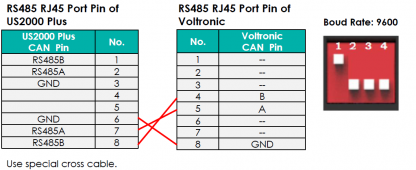
Page 31 of the Selpos Manual shows:

Does this mean 1/2 OR 8/7 pin pairs can be used? ( I have tried these both)
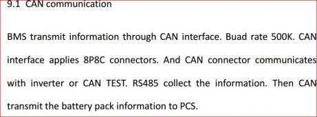
But then also in another Selpos Manual I can see:
I think RM485 is used for battery to battery comms is that right?

At the inverter end...
Axpert King / MMP Solar /
Reading online seems to show pins 5 and 4 are RS485A/B

So I tried the following:
Inverter 5/4 > 2/1 BMS
5/4 > 7/8 BMS
5/4/6 > 2/1/3 BMS
5/4/6 > 7/8/6 BMS
I then reboot all and set option 5 for battery in inverter to Pylontech - but all result in error 61 - no battery comms.
Also tried 4/5 , and BMS 1/2 , 8/7 (back to front) All get error code 61
Any ideas?
Sorry in advance but im stuck - I looked at the manual, but no matter what pins I try the inverter always fails with warning 61 (cant communicate with battery)
Steps taken: Set single battery pack DIP adress switches so 1 is set to 'ON' > Set inverter under option 5 to Pylon and confirm. Reboot Battery and then reboot inverter. Nothing - after 3 mins beeping error 61 to say no comms with battery.
Method : I have a RJ45 network cable I cut the end off and connected a special Rj45 cable with screw pins so I can easily change the wires around for pin out testing. I tested the pins once connected with multimeter to make sure pin out is as expected.
However ....
Page 31 of the Selpos Manual shows:

Does this mean 1/2 OR 8/7 pin pairs can be used? ( I have tried these both)
But then also in another Selpos Manual I can see:
I think RM485 is used for battery to battery comms is that right?

At the inverter end...
Axpert King / MMP Solar /
Reading online seems to show pins 5 and 4 are RS485A/B

So I tried the following:
Inverter 5/4 > 2/1 BMS
5/4 > 7/8 BMS
5/4/6 > 2/1/3 BMS
5/4/6 > 7/8/6 BMS
I then reboot all and set option 5 for battery in inverter to Pylontech - but all result in error 61 - no battery comms.
Also tried 4/5 , and BMS 1/2 , 8/7 (back to front) All get error code 61
Any ideas?
tigerwillow1
Solar Enthusiast
- Joined
- Sep 20, 2021
- Messages
- 194
My Seplos BMS RS485 runs at 19.2K. It's in the manual and I wasted a lot of time before finding that little detail. It also helps that my rs485-USB adapter has LEDs that show when data is being transferred.
USB adaptor? - I think you are referring to the other RS485 socket that is only used for direct PC communication?
The first RJ45 socket marked 'Canbus' (which can be programmed for Canbus or RS485 protocol depending on what you asked for when purchased) is the one used for direct Inverter connection to BMS.
The first RJ45 socket marked 'Canbus' (which can be programmed for Canbus or RS485 protocol depending on what you asked for when purchased) is the one used for direct Inverter connection to BMS.
tigerwillow1
Solar Enthusiast
- Joined
- Sep 20, 2021
- Messages
- 194
I saw the rs485 diagrams and tables a few posts up and assumed the ports labeled rs485, which I am using for PC communication. I don't use the canbus port. I never connected the dots that canbus can run on a rs485 link, until now. Looks like the canbus rate might be 500kbps, but you never know with chinglish manuals.


Hey guys! Would a Seplos 200A work on a 2P16S made of 32 pcs of 302Ah batteries, if I will use charge and discharge settings in the inverter lower tham 200A? The inverter is a Deye 12KW 3P. Can you define in Seplos BMS the total capacity of the bank, which exceeds 200A? (mine are ~600A)
On the inverter side I could define a max charging current of 120A and max discharge 190A.... should it be ok for the BMS?
On the inverter side I could define a max charging current of 120A and max discharge 190A.... should it be ok for the BMS?
Godo
New Member
- Joined
- Mar 21, 2022
- Messages
- 4
All, I have a 200A Seplos connected to a 16S battery, once connected I hit the reset button and all the lights go on, from left to right, then all on, off and on again and then light off one by one from left to right, during this time the screen goes on and shows "Seplos Battery System" and then...nothing, the screen unreactive, no lights, no nothing.
I've tried to connect the RS485 to the computer but with no luck so far.
Any obvious idea of what to do?
Thanks all!
I've tried to connect the RS485 to the computer but with no luck so far.
Any obvious idea of what to do?
Thanks all!
Godo
New Member
- Joined
- Mar 21, 2022
- Messages
- 4
Thank you tschini, I don't have a lab power supply for 48V (it only reaches 30V) so I guess connecting it to the inverter should do the same?.
I've got it to communicate (only a few seconds every time) and got 2 alarms "monomer high voltage alarm" and "Total pressure high pressure alarm", anyone knows what are those?
I've got it to communicate (only a few seconds every time) and got 2 alarms "monomer high voltage alarm" and "Total pressure high pressure alarm", anyone knows what are those?
RV10flyer
Solar Wizard
- Joined
- Mar 8, 2021
- Messages
- 1,198
I used three 6ga lugs with #10 hole. Same as 5mm.Wow! Tiny!
How do the shunt screws like a 50mm2 lug? I guess it will have to be a 6mm hole.
I'm planning to go for 50mm2 connections (with 3 x 16mm2 on the positive side) to keep the resistances down and by batteries are going to have to be 3m from the DC bus
Thanks Sergea
Kind regards
John
tschini
New Member
- Joined
- Jul 1, 2022
- Messages
- 4
Yes I hope so. I was also able to connect with the Windows software "Battery Monitor" and the adapter you get with the BMS during this initial 10 seconds where the BMS is running. So you could read out the parameters (total voltage, cell voltages, temperatures, warnings) before connecting the battery to the inverter.Thank you tschini, I don't have a lab power supply for 48V (it only reaches 30V) so I guess connecting it to the inverter should do the same?.
I've got it to communicate (only a few seconds every time) and got 2 alarms "monomer high voltage alarm" and "Total pressure high pressure alarm", anyone knows what are those?
I just used the USB adapter a Ethernet cable and the correct COM port with Baud Rate 19200 and you should be able to read the data before BMS turns off.
shavermcspud
Solar Enthusiast
- Joined
- Mar 12, 2020
- Messages
- 576
Have you trie to remove the can comms cable first, then power up?Yes I hope so. I was also able to connect with the Windows software "Battery Monitor" and the adapter you get with the BMS during this initial 10 seconds where the BMS is running. So you could read out the parameters (total voltage, cell voltages, temperatures, warnings) before connecting the battery to the inverter.
I just used the USB adapter a Ethernet cable and the correct COM port with Baud Rate 19200 and you should be able to read the data before BMS turns off.
sounds like the scenario when the battery is flat - not enough power to power bms.All, I have a 200A Seplos connected to a 16S battery, once connected I hit the reset button and all the lights go on, from left to right, then all on, off and on again and then light off one by one from left to right, during this time the screen goes on and shows "Seplos Battery System" and then...nothing, the screen unreactive, no lights, no nothing.
I've tried to connect the RS485 to the computer but with no luck so far.
Any obvious idea of what to do?
Thanks all!
Check voltage of each cell with a meter to see if one is flat - one of mine caused a lot of issues until I re-top balanced it.
houseofancients
Solar Wizard
if you are sure you have the rs485 version ( please post serial sticker) , it should be comnected to the port labelled canbus on the bms..hello, I have a voltronic Axpert MKS IV inverter, and bms seplos RS485, should the commencement cable with the inverter be connected to CAN or RS485A?
after set protocol in the bms , using the softwaee to RM485, and reboot bms.
after this change protocol on inverter to pylontech and reboot your inverter fully.
after this connect the bms cable ( make sure you use the correct pinout in the cable as it is port/device specific)
after all above is done correct, battery icon in display will start flashing, signaling the inverter is getting data from the bms
.
Similar threads
- Replies
- 6
- Views
- 1K
- Replies
- 2
- Views
- 291
- Replies
- 1
- Views
- 126
- Replies
- 9
- Views
- 880
- Replies
- 6
- Views
- 895


