diy solar

diy solar

Seplos CAN BUS RS485 48v 200A 8S-16S BMS

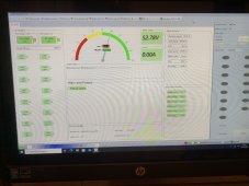
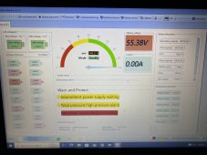
Thought I'd check on the system today and noticed that although the battery seems be charging ok from the PV, it's not charging at night (E7) and not really discharging during the evening. Looked back though the inverter history and it seems to have started this weird behaviour a couple of days ago. There are no faults logged on either the BMS or the Luxpower. Any ideas guys?
 
Seems to be in Standby mode too. How do I get out of that?
 

Attachments

  • 43376E86-474E-4C89-979D-55CEFE3DB416.jpeg
    43376E86-474E-4C89-979D-55CEFE3DB416.jpeg
    224 KB · Views: 29
Standby mode means that no charging/discharging current is flowing through the BMS. Start charging or discharging and it will change by itself.
 
I've just built my Seplos Mason 280 and reached 100% SOC for the first time when the below happened. I fully intend to read this thread and get caught up. But in the short term can anyone tell me if the below anything to worry about, as it looks catastrophic? It started with one cell initially and I assumed it was an issue with that cell, but then all cells intermittently started getting "Monnomer overvoltage protection".
 

Attachments

  • IMG_7280.JPG
    IMG_7280.JPG
    294.8 KB · Views: 36
I've just built my Seplos Mason 280 and reached 100% SOC for the first time when the below happened. I fully intend to read this thread and get caught up. But in the short term can anyone tell me if the below anything to worry about, as it looks catastrophic? It started with one cell initially and I assumed it was an issue with that cell, but then all cells intermittently started getting "Monnomer overvoltage protection".
If this is the 10E version (with bluetooth); momomer overvoltage protectiom and total voltage overvoltage protection are the only triggers for 100% capacity
I.e. the bms will reset to 100% whenever one of those is reached

In my case, I think my inverter uses the bms SoC value to know when to stop so I either charge to 100% each time and hit one of those protection or charge to something lower like 95% and only charge to 100% once a month or so… I guess I’ll do the latter


No mine is the '1101-SP16' if that means anything to anyone. I believe it's the model just before the bluetooth BMS. Perhaps that works in a similar way. Looks like i've got some reading to do.
 
No mine is the '1101-SP16' if that means anything to anyone. I believe it's the model just before the bluetooth BMS. Perhaps that works in a similar way. Looks like i've got some reading to do.
in that case, it looks like 100% is when it hits 56V, regardless of what you set in the parameters; so if your overvoltage protection is lower than 56V you will never see 100%; also if you set it higher than 100%, it will keep charging but still show 100%; and when you discharge it, it will show 100% for a bit until you go below 56V
at least based on what Andy says in his video

I think the behaviour is related to firmware version rather than model. I too have the same 2.8 firmware as Andy. That would explain it. It's sitting at around 54v and just switching my charge controllers on and off. I'll add this to the list of other peculiarities I need to investigate since my system went online yesterday.

I suppose this is half the fun and why we do it. ?
 
This is a quote from their site:

A:Not allow to upgrade the Firmware program without permission,after sales service is not available if its cause any damage.

Based on the above I suppose firmware upgrades are not a user-friendly thing and are used only in case of issues.
 
Well it looks like I’ve still got problems with my setup. Battery charges from PV and sometimes from E7 but is exceptionally flakey when it comes to discharging. Luxpower assure me that from the data, the inverter is calling for DC but the BMS just sits there in standby mode most of the time with a short token discharge when it feels like it. Guess I’ll have to try and get some sense out of Seplos ?
 
Check the voltage at the battery terminals after the BMS. If the BMS cuts out the discharge path you'll see low voltage there. I doubt that this is the BMS. If it is working correctly the discharge will not be limited unless the SOC is at 0% (which is the same as having a cell below the specified low voltage protection level).

And to confirm Andy's finding on the SOC drifting if you don't fully charge the battery pack regularly. I had about a month of battery use without getting to either 100% or 0%. Yesterday I charged it fully and found out that the SOC has drifted about 30% off.

How it went - during the charging process, the SOC got to 98.2% and then the battery took almost 100Ah before the SOC started moving up again. This happened as soon as a cell got to the 3.5V point (my high voltage warning threshold). When a cell hit the 3.6V (the high voltage protection threshold) the SOC got to 100% and the BMS disconnected the battery.

I never discharged below 45%. Seems like this has been 45% SOC at the beginning, but this has slowly drifted toward 15% before yesterday. My goal was to not get the battery completely drained during the cold months when I was trying to keep it warm and above 15C.

The algorithm utilized by the v16 BMS (10E) seems good on this. It can't easily track the SOC perfectly without frequently detecting the 0% or 100% SOC points. I like how it did not go to 100% before actually getting the cells fully charged. This would most likely prevent the inverter from further charging. I also like the approach for calibrating the 98.2% SOC at the point where the cells are hitting the warning threshold and the 100% SOC at the point where the BMS is hitting the protection threshold.

What would be better done would be to have more precise detection of the flowing current. But this would mean a shunt with higher resistance and more losses. To me, the design that Seplos took seems just right. I would also appreciate it if they include that detail in the documentation - I would know what to expect without having to reverse-engineer it.
 
Hello
I read about setting the BMS to ginlong
But I do not find this setting at all
I have a 10c.
 
I would ask Seplos to give you examples of communication with Victron or Fronius. I would not assume all CANBUS or 485 devices can communicate with each other unless you are an engineer who is familiar with those protocols. There is a user here who has successfully communicated with a Victron and an Orion BMS.
Check out Andy on his "offgridgarage" youtube channel to see if he has an update on his seplos experience.
 
No mine is the '1101-SP16' if that means anything to anyone. I believe it's the model just before the bluetooth BMS. Perhaps that works in a similar way. Looks like i've got some reading to do.
it is the 10e, i have exactly the same on my 10e.
bluetooth is part of the display and sold seperately
 
Did you ever manage to access the Bluetooth? If I do a scan using my iPhone, it can’t find it.
I managed to connect to it via iPhone; you need to download

I found it only works if I’m no more than 2m away from the BMS
 
Back
Top