diy solar

diy solar

Serial vs parallel Panels

HaldorEE

Solar Addict
Joined
Apr 20, 2020
Messages
1,633
Victron Energy has a short video on why their SCC don't start charging until the panel voltage is 5V > battery voltage. The presenter also explains why series wired panels are better than parallel wired panels from an energy harvesting standpoint.


In a different video he mentioned that the common advice to use parallel panels for better performance with shaded panels is incorrect. Bypass diodes in the panels mean that while a shaded panel doesn't add as much power as unshaded panels, they don't block other series connected panels from powering the system.

Has anybody experimented with shading parallel and series wired panels to see if this last statement is true?
 
After hearing someone's sales pitch to our company (manufacturer) about electronics per panel, I ran an experiment.
One of my GT PV inverters had two parallel strings of 9, 24V panels each.
I shaded one panel in one string. The power output didn't drop by 1/2 (9/18ths). It didn't drop by 2/18ths. It only dropped by 1/18th.

If I had shaded 4 panels out of 9 in one string, the power vs. voltage curve would have had two humps. A local maxima near full voltage and another possibly higher at half voltage. This is where two parallel strings on one MPPT suffers vs. two separate ones. A good MPPT algorithm will find the higher peak, a bad algorithm will stop at the higher voltage peak even if lower watts. Two separate MPPT, one per string, would be better in that case.

If you had four panels, each with two or 3 bypass diodes,
When wired in parallel, partial shading of a panel loses the entire production of that panel.
When wired in series, partial shading only loses the shaded (diode-bypassed) section of that panel; the illuminated portion of that panel and other panels still produce.

Only with a cell partially shaded do some manufacturer claims hold up. But it won't take long for the shadow to grow and at least one entire cell is shaded.

All this assumes the bypass diodes can handle full current. If not, and if partially shaded in full sun, series strings would burn up the diodes, and parallel would not. Some brands have problems but I don't know the names.

I go with series string, have eight strings each < 600Voc. Some are paralleled on single MPPT of an inverter.
I also have strings of varying orientation paralleled. SMA has measured and reported about 2% reduction in output due to less than optimum MPPT voltage for each string.
 
Multiple MPPT chargers could change things.

I was referring to the situation where somebody has a single charger that can handle two panels in series or in parallel. That is the situation where I have read advice that the parallel configuration is better for shading and now I think that advice is wrong.

I don't see why parallel would be better if you have bypass diodes in each panel. Without bypass diodes, parallel would be better.

Thanks for sharing your result @Hedges.
 
I don't see why parallel would be better if you have bypass diodes in each panel. Without bypass diodes, parallel would be better.
That seems like a detail to often overlooked.

I happen to have dual Growatts each with their own MPPT so I split my array in half, I can report that they frequently report 10-20% different watt numbers due to shading that affects one side of the array vs the other.
 
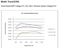
IMHO: 200W is the series vs parallel break point. Higher series voltage can drop MPPT efficiency by 1%-2% (EPEVER graphs), but offset by lower wire loss.
Parallel 200w / 17v = 11.76A, Series 200W / 34v = 5.88, 40ft of 10awg = 0.04 ohms, Wire power loss W =A * A * Ohms.
Parallel 40ft 10awg wire loss 5.53W,
Series 40ft 10awg wire loss 1.38W + 2% extra MPPT loss = 5.35W loss
 
MPPT has overhead, at low W in the efficiency drops, more so for higher voltage series panels.
tracer2210A.jpg
 
When building my solar tracker, I used 10 guage wires ran 60 feet to the panels / controller. Running 2s2p (4 panels), I would lose 40 watts due to the wire losses. (confirmed correct using a power loss calculator. While the actual conversion might be 4% less, the wire loss in my case was higher than the conversion loss. 1p3s runs up to 60 volts at 10 amps under max power.. 30 volts at 20 amps is too much for that wire and would require much larger wire (expensive), another trench and larger conduit to overcome. Overall efficiency for me is better at higher voltages.
 
When building my solar tracker, I used 10 guage wires ran 60 feet to the panels / controller. Running 2s2p (4 panels), I would lose 40 watts due to the wire losses. (confirmed correct using a power loss calculator. While the actual conversion might be 4% less, the wire loss in my case was higher than the conversion loss. 1p3s runs up to 60 volts at 10 amps under max power.. 30 volts at 20 amps is too much for that wire and would require much larger wire (expensive), another trench and larger conduit to overcome. Overall efficiency for me is better at higher voltages.
Right, your running 600w of panels and series panel wiring make sense as the wire loss is much larger than conversion loss.
 
Oh man, this is the first time I’ve heard about the loss of efficiency at higher voltages for the controller.

I have two 200W panels, each has a max power voltage of 20.4V (open circuit 24.3V) and max power current of 9.80A. Charging a 12V battery bank. 10 gauge wire 10ft to charge controller.

My MPPT has a max input of 50V and 30A. Right now I’ve got the panels in series for ~41V (48.6 open circuit). Am I correct that it’s generally a good idea to series the panels here to achieve the necessary charging voltage for more hours in the day, or am I just wasting power with the reduced conversion efficiency? I guess I also am planning on series to reduce wire gauge and therefore cost.

Thanks for the informative discussion!
 
I have two 200W panels, each has a max power voltage of 20.4V (open circuit 24.3V) and max power current of 9.80A.

My MPPT has a max input of 50V and 30A. Right now I’ve got the panels in series for ~41V (48.6 open circuit). Am I correct that it’s generally a good idea to series the panels here to achieve the necessary charging voltage for more hours in the day, or am I just wasting power with the reduced conversion efficiency?

It is generally an even better idea to make sure Voc absolutely, positively always remains below MPPT max input spec, even on a cold day.
Panel specs are given at 25 degrees C. The data sheet will show temperature coefficient, typically about -0.3%/degree. What is record cold temperature for your location? I use -15C (a bit extreme for San Jose, but conservative), so I assume -40 degrees relative to +25 nominal. That boost Voc 12% (for the assumed -0.3% tempco) and would put Voc > 50V.

But when Voc isn't violated (e.g. if you had a 100V controller and 3 panels in series), saving on wire cost and wire losses is worthwhile. You can do the math and look at charts for your controller, if the manufacturer is sophisticated enough to have the data.

Everything I run is designed for < 600 Voc (grid tied string inverters) and is nominally 480 Voc, 380 Vmp. I use 12 awg for single strings.
(One small setup has a 145V SCC with two "36V" panels in series. OK for this location but not Tahoe.)
 
Oh dang I didn’t even think about colder temps, good point! I do live where it gets very cold but I’ve been having trouble understanding how a mostly overcast winter affects the voltage, as in is max voltage rare when hazy/overcast or do the panels reach close to their max voltage even in half light?

The controller (Kisae DMT1250) has an over voltage shutdown above 50V, but I’m not sure how robust that protection is. Sounds like parallel might be the best bet to not fry the controller.
 
Panels reach near Voc with just a bit of light, because it is the response of a diode in conducting direction. For that reason, covering panels isn't sufficient to prevent a shock.

Mostly overcast reduces Isc and Imp in proportion to how much light.

Max voltage would occur on a cold morning with bright sun.

If you can determine that the controller has a max voltage spec 15% or so higher than 50V, simply doesn't operate and protects itself then you're OK. But don't count on words "shutdown" or "disconnect" without a voltage spec; when I've seen such words (for a different brand) and inquired, I was told it was a hard limit.

I don't see the exact specs you quote in the following link.


Your panels are a bit higher voltage than typical "12V" panels, which might be 17 Vmp and 21 Voc, so could be connected in series.
Parallel should be good for your panels and 12V battery. If you expand the system, consider the wide range of brands and voltages available (and support for 24V & 48V batteries, and various chemistries.)
 

Page 15, error code E03:

CH2 High Input Voltage Shutdown
This means the input from the CH2 Solar input has gone above 50V. This error will clear once the input drops below 48.0V”

I’m going to give them a call this week and see if it’s a hard limit of it it actually protects itself.

I didn’t realize how they are slightly higher voltage than typical until you pointed it out, which is a bummer in combo with this controller. So close to the right voltage! At least parallel will always work.
 
Oh man, this is the first time I’ve heard about the loss of efficiency at higher voltages for the controller.

I have two 200W panels, each has a max power voltage of 20.4V (open circuit 24.3V) and max power current of 9.80A. Charging a 12V battery bank. 10 gauge wire 10ft to charge controller.

My MPPT has a max input of 50V and 30A. Right now I’ve got the panels in series for ~41V (48.6 open circuit).

In Pappion's chart, the difference between 17Vmp and 34Vmp is only 1.5%

If your panels are flat on van roof, that orientation is optimal only when sun is overhead. Other times of the year, sun hits at an oblique angle so power is reduced. A tilt mount will boost output much more than that 1.5%

Panels in series need to be same current, same or similar orientation. With yours in parallel, you can orient differently, for instance aimed at 9:00 AM and 3:00 PM sun. That generates slightly less total power (orientation optimized for a time when sun passes through more air), but with 90 degree angle between them, peak power is reduced to 70% as much and hours of production are extended. That is useful if battery would otherwise reach full middle of the day and be draining early afternoon. It also lets you over-panel 50% beyond SCC rating without any clipping, because peak is within its rating.
 
I learned about this trick (orienting panels differently) by accident. (Constraints of a roof.) I'm finding that this solar stuff is as much art as it is science. If I hadn't tripped over this trick, I would have oriented all my panels to the south, and thought that that was the best that I could do.
 
Victron Energy has a short video on why their SCC don't start charging until the panel voltage is 5V > battery voltage. The presenter also explains why series wired panels are better than parallel wired panels from an energy harvesting standpoint.


In a different video he mentioned that the common advice to use parallel panels for better performance with shaded panels is incorrect. Bypass diodes in the panels mean that while a shaded panel doesn't add as much power as unshaded panels, they don't block other series connected panels from powering the system.

Has anybody experimented with shading parallel and series wired panels to see if this last statement is true?
I know this is an old thread but I had an interesting experiment over the last weekend with 2 of my 240W panels.

They are side by side and I was measuring their individual outputs as well as their combined parallel and series outputs. I got a result I could not explain (I am sure I am missing something?).

Individually, due to partial shading of 1 panel, I got 33.3V @ 7.05 amp (230W) for the non-shaded panel and 33.4V @ 0.32 (10W) amp for the partially shaded panel.

In parallel, I got 33.3V @ 7.3 amps. About 240W, makes sense.

In series, I got 66.6V @ about 7amps ... about 460W ... this doe NOT make sense to me. This was all measured with my DC clamp multimeter, either short-circuiting or measuring the output at the cabling attached directly to the panels. What am I missing? When connected to a charge controller, in series, is this when I will see the amperage/shading from the other panel affect the output?

I was assuming that with a saded panel or different shading on each of the panels that putting them in parallel would be best for output but my testing suggests the opposite ... right?
 
I know this is an old thread but I had an interesting experiment over the last weekend with 2 of my 240W panels.

They are side by side and I was measuring their individual outputs as well as their combined parallel and series outputs. I got a result I could not explain (I am sure I am missing something?).

Individually, due to partial shading of 1 panel, I got 33.3V @ 7.05 amp (230W) for the non-shaded panel and 33.4V @ 0.32 (10W) amp for the partially shaded panel.

In parallel, I got 33.3V @ 7.3 amps. About 240W, makes sense.

In series, I got 66.6V @ about 7amps ... about 460W ... this doe NOT make sense to me.
Something is wrong - the shade must have blocked most of one cell in the parallel test and switched to a smaller portion of two adjacent cells in the series test…
This was all measured with my DC clamp multimeter, either short-circuiting or measuring the output at the cabling attached directly to the panels. What am I missing? When connected to a charge controller, in series, is this when I will see the amperage/shading from the other panel affect the output?
So you were not actually messing output from an SCC with MPPT but just measuring Voc and Isc using a multimeter? That explains it then (more below).
I was assuming that with a saded panel or different shading on each of the panels that putting them in parallel would be best for output but my testing suggests the opposite ... right?
A solar cell will always put out Voc with the slightest amount of light when no current is flowing (measuring open-circuit voltage directly from cable ends using a multimeter). The presence of shading has pretty much no effect when measuring Voc (open circuit voltage).

And when + and - leads are short-circuited through a current meter, Isc (Short Circuit Current) will be measured with or without shade (at least if any portion of the panel at all is not completely blocked by shade).

Try putting that current source in series with a 50W power resistor of at least 40 Ohms and you’ll see a very different result..

A parallel string is really only superior to a series string if using a small number of half-cut panels.

With standard (full-cut) panels, as long as they battery voltage is below ~Vmp of a single panel -1.8V, a good MPPT can activate 1, 2, or even all 3 bypass diodes of a partially-shaded panel, resulting in full Isc x Vmp for the unshaded panel plus ~2/3, ~1/3, or 0% output from the shaded / bypassed panel (minus an additional factor of ~0.6V x number of bypass diodes activated).

In a parallel configuration of standard panels, the unshaded panel ‘clamps’ the partially shaded panel at full Vmp, resulting in 0% output from the partially shaded panel even if only two full cells in differing sections are shaded (because no bypass diodes can be activated). So with cells within 2 bypass sections blocked, output will be close to 50% (100% from the unshaded panel and about -5% or so from the shaded / bypassed panel).

If only a single cell is shaded, a good MPPT can reduce voltage to 2/3Vmp - 0.6V to activate one bypass diode on the partially shaded panel. That panel will have (2/3Vmp - 0.6V) x Imp of output or about about 65% of full output while the unshaded panel will have it’s output reduced to (2/3Vmp - 0.6V) x Isc since voltage will also be reduced but current can increase from Imp to Isc in partial compensation. That’s usually translates to at least 110% the output of the singly-bypassed / partially-shaded panel so (65% + 71.5%) / 2 = ~68% of max output from the full 2P string. Because 68% of max output is > 50% of max output, a good MPPT will ‘find’ the advantage of lowering string voltage from Vmp to 2/3Vmp - 0.6V to activate a single bypass diode on the partially-shaded panel.

If your considering getting a string composed of a small number of half-cut panels, there are advantages to a parallel string over a series string, but I’ll save that for another post (and only in the case you’ve identified some half-cut panels you’re ready to pull up he trigger on..).
 
Something is wrong - the shade must have blocked most of one cell in the parallel test and switched to a smaller portion of two adjacent cells in the series test…

So you were not actually messing output from an SCC with MPPT but just measuring Voc and Isc using a multimeter? That explains it then (more below).

A solar cell will always put out Voc with the slightest amount of light when no current is flowing (measuring open-circuit voltage directly from cable ends using a multimeter). The presence of shading has pretty much no effect when measuring Voc (open circuit voltage).

And when + and - leads are short-circuited through a current meter, Isc (Short Circuit Current) will be measured with or without shade (at least if any portion of the panel at all is not completely blocked by shade).

Try putting that current source in series with a 50W power resistor of at least 40 Ohms and you’ll see a very different result..

A parallel string is really only superior to a series string if using a small number of half-cut panels.

With standard (full-cut) panels, as long as they battery voltage is below ~Vmp of a single panel -1.8V, a good MPPT can activate 1, 2, or even all 3 bypass diodes of a partially-shaded panel, resulting in full Isc x Vmp for the unshaded panel plus ~2/3, ~1/3, or 0% output from the shaded / bypassed panel (minus an additional factor of ~0.6V x number of bypass diodes activated).

In a parallel configuration of standard panels, the unshaded panel ‘clamps’ the partially shaded panel at full Vmp, resulting in 0% output from the partially shaded panel even if only two full cells in differing sections are shaded (because no bypass diodes can be activated). So with cells within 2 bypass sections blocked, output will be close to 50% (100% from the unshaded panel and about -5% or so from the shaded / bypassed panel).

If only a single cell is shaded, a good MPPT can reduce voltage to 2/3Vmp - 0.6V to activate one bypass diode on the partially shaded panel. That panel will have (2/3Vmp - 0.6V) x Imp of output or about about 65% of full output while the unshaded panel will have it’s output reduced to (2/3Vmp - 0.6V) x Isc since voltage will also be reduced but current can increase from Imp to Isc in partial compensation. That’s usually translates to at least 110% the output of the singly-bypassed / partially-shaded panel so (65% + 71.5%) / 2 = ~68% of max output from the full 2P string. Because 68% of max output is > 50% of max output, a good MPPT will ‘find’ the advantage of lowering string voltage from Vmp to 2/3Vmp - 0.6V to activate a single bypass diode on the partially-shaded panel.

If your considering getting a string composed of a small number of half-cut panels, there are advantages to a parallel string over a series string, but I’ll save that for another post (and only in the case you’ve identified some half-cut panels you’re ready to pull up he trigger on..).
Thank you for the post.

I can confirm the shading did not shift significantly over the test period. I think you know the issue is related to other things.

Yes, It was just measuring VoC, Isc with no load.

I understand that the VoC would not change with shading. The data also supports this. I can also confirm that the Isc is hugely impacted by the shade. When tested individually, the partially shaded panel has an Isc of only 0.32 amps. The unshaded, 7.05 amps. I was confused or am missing something when it comes to putting the 2 panels in a series ... I was expecting to see a drop in the Isc (just like the individually shaded panel) but I did not see this. I assume this is an artificial test situation and is as expected and that under load/when charging, I will actually see a drop in the amperage and so wattage from the series-connected panel. When put in parallel the panels behave as you would expect, no change in VoC, and Isc of both panels combined.

I would have assumed that in the below situation that a parallel setup would give me the most power production over the course of the day due to the differential shading each panel receives, over a series connection. I was testing to see if this was going to be the case but it seems my testing is not going to show me real-world results.

How would the panel that, individually is only producing 0.32 amps, be better in series than in parallel? wouldn't it in series negatively affect the output from the fully-shaded panel? I expect from the parallel test that I would, more or less, get an output that matches the individually tested panels. Is this faulty logic?

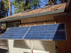
PXL_20211107_194329273.jpg
 
Thank you for the post.

I can confirm the shading did not shift significantly over the test period. I think you know the issue is related to other things.

Yes, It was just measuring VoC, Isc with no load.

I understand that the VoC would not change with shading. The data also supports this. I can also confirm that the Isc is hugely impacted by the shade. When tested individually, the partially shaded panel has an Isc of only 0.32 amps. The unshaded, 7.05 amps. I was confused or am missing something when it comes to putting the 2 panels in a series ... I was expecting to see a drop in the Isc (just like the individually shaded panel) but I did not see this. I assume this is an artificial test situation and is as expected and that under load/when charging, I will actually see a drop in the amperage and so wattage from the series-connected panel. When put in parallel the panels behave as you would expect, no change in VoC, and Isc of both panels combined.

I would have assumed that in the below situation that a parallel setup would give me the most power production over the course of the day due to the differential shading each panel receives, over a series connection. I was testing to see if this was going to be the case but it seems my testing is not going to show me real-world results.

How would the panel that, individually is only producing 0.32 amps, be better in series than in parallel? wouldn't it in series negatively affect the output from the fully-shaded panel? I expect from the parallel test that I would, more or less, get an output that matches the individually tested panels. Is this faulty logic?

View attachment 71849
For a situation where at least one cell in every volume is completely shaded, there is little difference between parallel and series.

In parallel, you’ll get 100% output from the unshaded panel and close to 0% from the shaded panel, or an average of 50% from the string (current of ~Imp @ voltage of Vmp).

In series, as I explained earlier, string voltage will drop from 2xVmp to 1x Vmp - 3 x 0.6V.

The unshaded panel will still be putting out Isc a full Vmp, but the shaded panel will actually be putting out Isc at minus 3 x 0.6V = -1.8V (since three bypass diodes have been activated to supply Isc by bypassing the tree sun-strings of the shaded panel).

So total power is (100% + ~-5%) / 2 = ~47.5% (95% of the power from a parallel string).

I already explained how things change if only 2/3 of the shaded panel is covered (meaning at least one cell fully shaded in 2 out of 3 2-column bypass sections). In that case, the parallel string still puts out 100% while the shaded panel puts out 0% for a string average output of 50% while a series string will activate 2 bypass diodes on the shaded panel to deliver full Isc @ Vmp/3 resulting in (100% + 33%) / 2 = 67.% output for the string (33% higher output than the parallel string), [precise power needs account for the same -1.2V drop from 2 bypass diodes being activated, so actual output of the shaded panel will be closer to 30% for full string output of ~65%]

And I’ll use your photo to tell you the impact of half-cut panels can have;

That same shade you’ve photographed on two half-cut panels in series will have string output of over 50% from both panels for string output of 50% (actually a bit higher since voltage of the unshaded panel will increase from Vmp to Voc for a ~10% output gain and string output closer to 55%), so similar to a series string of conventional panel but actually 15-16% higher once you dig into the details.

More importantly, in a parallel string of half-cut panels, the unshaded panel will deliver exactly 100% power while the shaded panel will deliver exactly 50% power for a string output of 75% (over 36% better than the same half-cut panels in a series string and a whopping 58% better than conventional panels in a similar series string).

I’m facing a severe morning shading issue with all 3 panels covered by shade in the way you’ve indicated (but in portrait orientation and only across the bottom half of the panels).

I get 50% output during that shaded period from a 3P parallel string where I’d get 0% output from the entire array as long as there are no 2-column bypass-diode sections free of belong blocked by shade…
 
Back
Top