diy solar

diy solar

Series/Parallel - Questions....

tucsonsolar

New Member
Joined
Feb 25, 2020
Messages
24
Hello.....new to all this....

Putting in an MPP 2424 inverter with the following specs...

It has a Max PV Array Input of 145V DC and a Rated power of 2000 W. My array would be 4-327 W panels, so well under the rated power listed.

Panels I'm considering are Max Power Voltage - 54.7V and Open Circuit Voltage of 64.9. Don't know which one should be used for calculations, so I defaulted to the higher....

If the panels are mounted in series, I can only do 2 at a time, coming in at 129.8 input voltage coming from 2 panels.

Question - can 2 sets of 2 panels be combined in a serial fashion and then just connected through something like an MC4 connector to hook into the inverter and would this be safe or would this combine the 2 sets of serial voltages and exceed the input max of the inverter?

What would be the easiest (smartest) way to connect this set of 4 panels? I've bought the BigBattery 24v powerwall lithium system and just want to power a few appliances in the house and have a backup in case of emergency....Would a complete parallel configuration make more sense? I always plan to have grid backup unless it's not available to keep batteries charged.....

The wiring of this is just getting me stuck....I would also appreciate any help with ideas on the wiring and parts needed to assemble this in the most sensible and easy to accomplish fashion...

Thanks! Michael in Tucson....PS - if there's any locals, I'd buy lunch for a bit of help....
 
Yes. What you are describing is 2s2p.

The 2 series panels will combine as you noted. Voltage adds in series, current stays the same.

Then you take those 2 sets and put them in parallel with a combiner box. Parallel adds the current and now voltage remains the same.

There is a wealth of info and help on this forum to help you get it done.
 
I would prefer the simplest solution....If I can do it with MC4 Y connectors and not have to worry about exceeding any electrical limitations, this seems far simpler and easier to me....I could use some advice here.....would taking the 2 X 2 set of panels run in series and connecting them through a MC4 Y connector back to the inverter solve my issue? Sure hoping it would....

THanks!
 
not have to worry about exceeding any electrical limitations
You only have to strictly worry about exceeding these limitations for the Y connectors:

  • CE and TUV certified Hard plastic;Protection Class: Class II Temperature Range: -40C~+90 C
  • One FFM; one MMF Withstanding voltage: 1000V DC(TUV), 600V(UL)

You're squeaking by under these numbers, by a LOT.
 
So I have this in my mind.....2 sets of 2 panels each, producing 129.8 v output voltage from each set, each set wired in a serial fashion.

My inverter has an incoming limit of 145V DC. This is where my electrical overload concerns are.....

I could then connect the output of each set of panels into a 4 way MC4 Y connector which can then connect directly into the inverter, without the need for a combiner box. Is this process in effect wiring the sets of panels in a parallel fashion?

This is my first try, so I'm really trying not to miss on the wiring and cause damage to the system.

Can someone confirm this is OK? Much appreciated.....
 
129.8 is less than 145 so you are OK IMHO.

I believe most of us try to run the MPPT's near the top end of the voltage range where I understand they are most efficient. Your unit may have a graph in the user manual that confirms this.
 
I meant 2 - 2 way MC4 Y connectors - this would provide the positive and negative leads going to the inverter.....
 
Panels I'm considering are Max Power Voltage - 54.7V and Open Circuit Voltage of 64.9. Don't know which one should be used for calculations, so I defaulted to the higher....
These two parameters are used for two different things:
  1. Your SCC will have a Maximum PV Voltage, use Voc.
  2. Your PV cables and connectors need to be spec'd for operating conditions, use Vmp and Imp.
  3. You PV cable should be able to support fault conditions (i.e. short circuit), use Isc.
Question - can 2 sets of 2 panels be combined in a serial fashion and then just connected through something like an MC4 connector to hook into the inverter and would this be safe or would this combine the 2 sets of serial voltages and exceed the input max of the inverter?
No. You just wouldn't connect PV panels directly to an inverter. Why?
  1. The maximum power from a PV array only happens at a very specific load, your inverter would represent a varying load so it is unlikely you would ever make efficient use of your array.
  2. Your inverter would undoubtedly be connected to your battery. Having a voltage higher than 14.4V will damage your battery (note: it might seem to work OK until the battery nears a full charge).
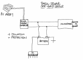
I would recommend that you take a look at Will's system blueprints but, in summary, this is a basic off-grid solar setup.

basic solar.png
So I have this in my mind.....2 sets of 2 panels each, producing 129.8 v output voltage from each set, each set wired in a serial fashion.
Your array connection topology is sound, 2S2P makes sense.

Other considerations:
  • Your 1,308W array is capable of generating 55A at 24V (nominal). Make sure your battery and BMS supports this.
 
You only have to strictly worry about exceeding these limitations for the Y connectors:

  • CE and TUV certified Hard plastic;Protection Class: Class II Temperature Range: -40C~+90 C
  • One FFM; one MMF Withstanding voltage: 1000V DC(TUV), 600V(UL)

You're squeaking by under these numbers, by a LOT.
I'm coming up with 5.039A for 64.9V at 327W. Or 0.156A over the UL 20A rating for MC4 conectors.
I love the Ohms Law Calculator App on my phone. Just plug 2 of the numbers in and out comes the rest.
 
Another question - I plan to run my PV wire (hot line) through a single pole circuit breaker before feeding it into the all in one inverter (LV2424). I think a 15A breaker would be fine but should that be a different number? I'm running my Powerwall 24v (3kwh) battery through a 40A single pole circuit breaker before it connects to the inverter....

Thoughts???
 
I think a 15A breaker would be fine
Your panels 327w / 64.9v = 5.04 amps. per string.
2 strings in parallel is 10 amps so a 15 amp breaker is perfect.

40A single pole circuit breaker before it connects to the inverter....
What inverter are you referring to? (Take its max wattage and divide by volts to get max amps. Get next bigger amperage breaker (+25% good rule of thumb)).
 
I personally wouldn't bother fuse/CB-protecting a PV run, so long as the PV cable you are using is rated for at least Isc (PV Current Short Circuit). An isolator switch? Yes. Fuse/CB? No. In other words, the 'number' doesn't matter (except for nuisance breaking below Isc).

To illustrate my point, if Isc was, say 9A, if you put a 10A breaker in-line it will never ever trip.

The only caveat to this is if you have a very large array where a short could potentially backfeed through other panels. This is the only scenario I would consider having any circuit protection on a PV cable run.

Other opinions are available!

Edit: simplified wording.
 
Last edited:
p.s. Oh, lighting strike protection, maybe, but tbh if you get a lightning strike neither fuse nor CB is going to protect your PV system. You're fucked.
 
I personally wouldn't bother fuse/CB-protecting a PV run, so long as the PV cable you are using is rated for at least Isc (PV Current Short Circuit). An isolator switch? Yes. Fuse/CB? No. In other words, the 'number' doesn't matter (except for nuisance breaking below Isc).

To illustrate my point, if Isc was, say 9A, if you put a 10A breaker in-line it will never ever trip.

The only caveat to this is if you have a very large array where a short could potentially backfeed through other panels. This is the only scenario I would ever consider having any circuit protection on a PV cable run.

Other opinions are available!

Edit: simplified wording.
What about something like this, use it as a switch?

https://www.amazon.com/KUMEED-Inlin...B41ND8JV1RX&psc=1&refRID=3EMVTMW3QB41ND8JV1RX
 
Those things are infamous. Wouldn't use, would never recommend.
 
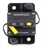
Those devices (cheap in-line circuit breakers), they are known to fail (melt, catch fire etc) i.e. infamous, even when used within specs. There's a recent thread on here about them, which included a recommendation for a particular brand... they look like this:
1583434192608.png
... but I can't remember the brand, it had a double-ganged name, if memory serves. Water proof, marine-grade...
 
Those devices (cheap in-line circuit breakers), they are known to fail (melt, catch fire etc) i.e. infamous, even when used within specs. There's a recent thread on here about them, which included a recommendation for a particular brand... they look like this:
View attachment 8586
... but I can't remember the brand, it had a double-ganged name, if memory serves. Water proof, marine-grade...

Bussmann, and the thread is here: https://diysolarforum.com/threads/newbie-troubleshooting.4985/ ;)
 
Back
Top