diy solar

diy solar

Series String Wiring Question

Just to add to this, I have created a universal string sizing tool that will work with GT inverters and Charge Controllers. You can string size with any inverter or charge controller type.

string-sizing

Feedback on your sizing tool:

It appears to make recommendation based on STC rating of panel, not PTC, so it undersizes the array.

I entered a "custom" inverter for 10,000W (because you only have a couple recent models ready-made.)
I selected SunPower E20 327W from your list.
The tool recommended 7s4p. When I pumped it up to 8s4p, it said,

"10464, Over the Inverter Max Power of 10.00kW with Oversize Factor of 1, Max Should be: 10.00 kW, You have 10.46 kW"

That's only 4% over, and based on STC ratings which of course are rarely achieved.
Your tool ought to use PTC ratings to suggest an array which drives the inverter to full power.
Given voltage and short-circuit current limits, you could also recommend a maximum over-paneled configuration.
We often consider that to get additional power off-season and longer in the day.

Many people have non-ideal orientation. In that case you could recommend a larger array to still reach maximum output.
And finally, some of us use multiple orientations of strings, wired in parallel (or into multiple MPPT) for "passive tracking".

First of all, thank you so much for checking out the tool! ?That's great.

I used STC because I wanted the datasheet to be consistent. Module datasheets can display their information differently whether it's labeled PTC or NOTC, but they always have STC values. I think I will include your suggestion on new entries and just have [STC], [NOTC] or [PTC] label at the end of the name so you know what you are selecting , and can select what you want if those values are available for that model. Thanks for that feedback!

For the oversizing portion, that's why I added the oversizing factor (Advanced Portion) so that you can oversize it up to 150% , if more is needed I can easily update that to be larger. The tool allows oversizing , but just has a warning in case you weren't aware you have oversized it if it wasn't intentional. Perhaps the improvement of the [PTC] modules will help with that as well.

I didn't quite understand what you mean by multiple orientation of strings.
 
I didn't quite understand what you mean by multiple orientation of strings.

10kW of PV panels aimed at Noon sun produces 10 kW.

Split in half, 5 kW aimed at 9:00 AM and 5 kW aimed at 3:00 PM, 90 degrees apart, present 0.71 times as much area toward the sun.
There is also reflection off the glass, so I don't know the exact impact, but nominally I expect it to produce 7.1 kW
(That is convenient for people limited to 40A breaker, 32A continuous current.)
With 10 kW of panels, peak current is about 7 kW and power is spread out over more hours.

These panels of two different angles can't be connected in series, of course. They can be connected in parallel or to two different MPPT inputs.
 
Well then, I'm completely wrong. Thanks for the clarification. I thought panels had blocking diodes in addition to bypass diodes.
The PV cells themselves *are* diodes, but there are also "bypass" diodes which help reduce loses in partially-shaded situations. I don't think the bypass diode would be doing anything in the scenario OP is describing.

This illustration is helpful:

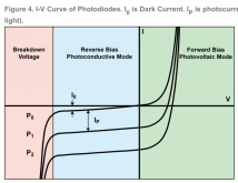
I'm surprised this thread got so far without anyone posting an I/V curve of a diode. Figure 4 here is a standard I/V curve: https://www.teamwavelength.com/photodiode-basics/, reproduced here:

Basically "Voc" is the x-intercept in the green region. Power production is the 4th quadrant (bottom right quadrant). If you go beyond Voc, it's still a diode, and it will start to dissipate power (current becomes positive, as opposed to negative). So if the MPPT tracks to a maximum-power voltage which exceeds the Voc of the 3s panels, they will become power sinks as opposed to power sources. Now, PV diodes are probably not designed to sink very much power and at some point this would break them.

Long version if you don't get it:
Just imagine MPPT is increasing the voltage of all paralleled strings, so it walks along the curve from y-intercept (teal/green boundary) to x-intercept (in green zone). Typically it would stop at the "knee" which is the maximum-area rectangle you can subtend within the I/V curve, maximizing power. But, for the 3S, they have the same voltage divided by 3 instead of divided by 4, so they walk further to the right, potentially crossing upwards into the first quadrant (upper right) and then dissipating power.

Other key point: this "family" of curves is for 3 different illuminations. The lowest one is in the most illumination. The upper one is in darkness.

1615191692041.png
 
Last edited by a moderator:
So if the MPPT tracks to a maximum-power voltage which exceeds the Voc of the 3s panels, they will become power sinks as opposed to power sources.
I should add that if they do not cross that far, they will still produce power but just not very much power since they're above their optimal voltage. Without calculating the actual crossover point for your particular panels, in general I wouldn't risk it: series strings connected in parallel should all have the same number of panels.
 
Back
Top