diy solar

diy solar

Setting Up a Dual Pole Circuit Breaker

chrisski

Solar Boondocker
Joined
Aug 14, 2020
Messages
5,174
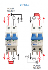
This picture shows the left side wires the wrong way. This is the wrong way to set up a dual pole circuit breaker:
Dual Pole Circuit Breaker-Danger Wires Reversed.jpg

Picture may make it hard to see, but the wiring is wrong. Wiring needs to be set up so the positive wires go on one side (Top), and negatives wires go on the other side (Bottom). The + does not mean put the positive wire here and - means put the negative wire here. The plus and minus are to be sure the wires are set up so the current flows through the circuit breaker the correct way.
 
Last edited by a moderator:
Note that he's talking about a "polarized" DC breaker".

It's also not that the wires just need to be opposite, they need to be opposite polarity on the load side and match polarity on the power side.
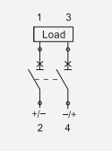
The current direction is important to manage the "arc-chute". Here's an easier to see image from Altech, note how the current flows the same regardless of the side the load is on:
1604840674029.png

There are non-polarized DC breakers too, but always read the instructions carefully ... sometimes one side will be marked "B" or "Batt" or perhaps "Load" or "aux".

Also ran across this testing blurb from Midnight: http://www.midnitesolar.com/pdfs/MidNite_165vdc_ETLtest.pdf
 
Last edited:
Interesting story on Midnight's testing.
2000A is 1/5 what the breaker is supposed to interrupt (10kA) so an insufficient test.
I didn't follow "fuse in parallel with 6 awg". That would divide current between those two parallel paths.
Goal was to ensure power didn't arc to enclosure. I think that should have been current from battery loops though breaker and back to battery, and enclosure grounded to battery negative with fuse. Any arc to enclosure would then go through fuse.
No diagram provided, just trying to figure it out from the words.

The knife switch he's using doesn't have spring loaded snap action.
I've got one rated 200A, 600V AC/DC which would work for the 165V 99A overload test.
It can carry the fault current of a short long enough for a fuse to clear it, but isn't meant to interrupt the current.
Good thing the Midnight guys got breaker polarity correct before trying short circuit test.
 
I wrote to Midnight about polarity of breakers for an SCC. Here was their response:

"On the MNEPV Circuit breakers the (+) on the PV IN for the Classic goes to
the PV array positive. The (+) on the battery out breaker of the Classic
goes to the Battery. The 60 or so volts on the battery side have little or
no arc to extinguish. On the PV side we mostly are concerned with
extinguishing the arc when the circuit breaker is manually turn off for
maintenance. If there is a catastrophic event in the PV array they causes
backwards current flow to trip the PV IN Breaker you are going to having
bigger issues than a burned up PV in breaker."

But once I assemble PV array, it can never produce more than Isc (plus a bit for extra illumination from clouds), so oriented to interrupt current from PV panels, it'll never experience overload that way.

Fuses or breakers on PV panels are for protection against backfeed. If I have 6 PV strings in parallel, all producing 7A and each protected with 15A breakers, the fault to consider is a short within one string (which could be diodes failed shorted.) In that case, 5 x 7A = 35A flows backwards into the array.

If you manually turn breaker off for maintenance (as Midnight mentions), and current is flowing when you do so, that's the situation where they had a failure on their first attempt because it was backwards (carrying 150% of rated current.) Orienting the breaker per their recommendations allows hot switching to be reliable.

However, interrupting current backfed into one string, which is why OCP is required for 3 or more parallel strings, it isn't going to work.

I believe a solution could be to orient breakers for protection against backfeed into array. And never hot-switch them; turn off charge controller first. Disconnecting from battery could be the way, BUT, some charge controllers may not want PV connected and batteries disconnected.

AND, that breaker between battery and charge controller is oriented to interrupt current backfeeding into charge controller from battery. If you open the breaker while high charge current is flowing, that direction doesn't work well for the breaker. (However, Midnight indicated the ~ 60Voc at battery wasn't such a big problem for arcing. And of course when opened with charge current, voltage from charge controller wasn't much higher than battery. Inductive kick from MPPT might arc briefly but would stop; the kick is more of a problem for MPPT electronics than the breaker.)

You could use a 2-pole breaker between charge controller and battery, wired so one has the correct direction of current flow for its arc chute. And each pole is rated for full voltage of battery. That would ensure arc in either direction could be extinguished.

The saving grace for my system is that the PV breaker is ganged 6 pole. If I connect per Midnight's recommendation, arc chute works when opened during charging. In the event of a short in one string, that breaker opens due to overload. While it's arc chute doesn't work, the other 5 ganged breakers also open and each successfully interrupts its current (those aren't even overloaded, rather carrying 50% of rating.)
 
I believe a solution could be to orient breakers for protection against backfeed into array. And never hot-switch them; turn off charge controller first.
THe three different charge controllers I have do not have a way to power them down. Does yours have a switch? Only way to power down my charge controller would be to physically remove the wires, and that has it’s own issues like shorting to each other or the ground, or arcing Especially if left too close to the controller.

When I’m not at the RV, I remove power from the solar panel circuit breakers and then shut the battery off. If the RV is in storage where I can’t get to it for a week, I will pull the batteries. Not really practical to cover the panels to stop power. THis is my procedure now, but I’ve only had the solar turned on for a couple days testing and shut it off whenI leave.

I have been using the circuit breakers to remove the power from the solar panels, and after that is done, I switch off the main battery switch. The roof panels have 48 VMC and 6 amps ISC. I have two strings of those going to one charge controller and the other charge controller has panels putting out 22 volts, although they are rated at 18 VMC, with an ISC of 6 amps, and four in parallel (22 volts at 24 ISC total).

If this were 250 volts of solar with 20 amps, I certainly would not be playing with the circuit breakers, but I think my procedure now is good.
 
Last edited:
THe three different charge controllers I have do not have a way to power them down. Does yours have a switch? Only way to power down my charge controller would be to physically remove the wires, and that has it’s own issues like shorting to each other or the ground, or arcing Especially if left too close to the controller.
Right, mine doesn't either.

My original setup was grid-tie. SMA recommends turning off AC breaker first. My inverters either have a 30A 600V AC/DC heavy duty snap-action knife switch, or the rotary switch in SMA disconnect for DC. I believe those can interrupt their rated currents (but not excessive fault currents).

Fuses are good. They're never supposed to blow. My transformerless grid-tie inverters have fuses at both ends of each PV string.
My Sunny Islands have a DC breaker built in. They would be limited to about 140A charge current but have to interrupt fault current. Come to think of it, they are 2-pole. I put class T fuses at the battery.

The mobile unit I'm assembling is my first time wiring DC breakers, and uses Outback/Midnight breakers. Now that I've thought enough on the topic and communicated with Midnight I can make that work. I'm using "Sunny Island Charger" from MSTE, 140Voc PV to 40A 48V battery charge current. Wire 63A battery breaker to protect again backfeed of fault current, and don't hot-switch. PV breaker is 6 pole ganged, 100 Voc. Wire PV breaker to interrupt current from PV to SCC, and the fact it is ganged lets it function with either direction of current flow.

I think a 2-pole breaker between SCC and battery could be used to interrupt current in either direction. Could be wired in positive and negative wires, or back-to-back in the positive.

Midnight sells 2 pole breakers for use with higher voltage PV strings. Wired instead as back-to-back or interrupting both positive and negative, I think that would allow switching & OCP of current flowing in either direction, but only at the lower voltage rating of a single breaker.
 
A high wattage system 2k or 3k is years away for me, so I have not planned a lot, but I think I’d go with a disconecting switch and fuses versus the circuit breakers I have now where there’s a max of 300 watts through two of them, and 400 watts through the third.

I do see that Midnite solar has a variety of disconnecting combiners for sale. If I went with a system pushing out a lot of watts, that’s probably what I want going to each of my charge controllers. Since I would not be flipping circuit breakers, I would go with fuses on that. With thousands of watts of power going to that disconnecting switch, I’d probably not trip it on or off unless it was sark or cloudy.

I want to upgrade to 24 volts for my RV, and after that, would be an Offgrid cabin with 2kw or 3kw of panels. Between now and then, I would need to get some support from the other decision maker in the family, and lets just say, she’s not as excited about this as I am.
 
Just save up your lunch money. 2kW PV can be had for $400


Those particular panels are best for ground mounts rather than on the building, given that UL labels were removed.

8 panels as two strings of four, 4S2P, no fuses needed. But a 250 Voc SCC will cost more than the panels.


That charge controller would support 2 kW into 24V, 4 kW into 48V battery.

Multiple fused strings into a less expensive hybrid inverter could be the economical setup.
I use 600 Voc strings into AC coupled inverters.
 
For this cabin that’s not built Yet on land I don’t own yet, I’m going to take some time to think on what I want to do. I did learn from my RV build to not chase after good deals unless these deals fit my end plan. I got a really good deal on one panel for my RV build, but spent a bit of time hunting three more deals down, and when I went to set them up, theSe four panels were really lacking things like documentation, MC4 connectors and a couple of other things.
 
Last edited:
"linked the wrong article."
Yup, missed the ^C copy. Fixed now.

The SunPower 327W I got are great for my home system (8 in series for < 600 Voc) but don't match a 140Voc SCC I want to set up mobile. Two in series would exceed Voc if I drive to a cold area. One panel is too low voltage.
There are some 435W panels which would fit the voltage range and span the width of the vehicle.
 
Why wiring your breaker properly is vital.

 
What about using non-polarized circuit breakers like this one?

Is it non polarized because it doesn't have an arc chute (a.k.a. arc extinguisher, snuffer comb, etc.)?

Is it important to have an arc chute? I read somewhere that the arc chute is designed to minimize damage to contacts, but that they should separate enough such that the arc eventually stops.
 
Last edited:
What about using non-polarized circuit breakers like this one?
I have no idea if its good. Mentions this standard: Standards : IEC 60947-2/ EN 60947-2.

Because of testing, I'm sticking with my much more expensive midnite solar circuit breaker


I'm not brave enough to pioneer new trails. The reviews on the Amazon site do not have a lot of details. The C/B does look like others I've seen marketed like the C/B inside the pre-built Ecoworthy Combiner boxes.
Is it non polarized because it doesn't have an arc chute (a.k.a. arc extinguisher, snuffer comb, etc.)?

Is it important to have an arc chute? I read somewhere that the arc chute is designed to minimize damage to contacts, but that they should separate enough such that the arc eventually stops

I don't know that either. I do look for my C/B to come from a quality company like Blue Sea or Midnite Solar that have built them to an accepted US standard and are in wide use. However that is achieved whether its an Arc Chute or not, I don't know. I look for both the C/B rating like 100 amps so it will pop above that, but also an AIC rating greater than my batteries can push out so the breaker does not trip and arc across it.

The one you linked does not list AIC, but does list Breaking capacity (Icu):10 kA, which I don't know if that's equivalent.

The midnite solar is rated to turn on and off as many times as you want.
 
I have no idea if its good.
Your thoughts on standards and brands are appreciated. However I am more interested in the concept of non-polarized breakers in general. Can using non-polarized breakers eliminate the dangers and complexities of polarized breakers (such as those considered by @Hedges above)?

I didn't read the full article you linked to, but MidNite Solar claims the MNEDC-300 Non Polarized Breaker can "break the full rated load at the rated voltage repeatedly, with NO DAMAGE".

Compared to a breaker like that, do polarized breakers have any advantages?
 
I would have went with a non-polarized breaker had I known better. I got the polarized breaker because I heard that a two wire breaker broke the arc of the wire in two directions which was even better. I did not know about the down sides of a polarized breaker Being a fire hazard.

There’s a YouTUbe video from a solar installer in Australia that says polarized breakers aren’t used there anymore. He comes across old installations where these these things have been improperly installed and are fire hazards.
 
There’s a YouTUbe video from a solar installer in Australia that says polarized breakers aren’t used there anymore. He comes across old installations where these these things have been improperly installed and are fire hazards.

Yes. I believe gnubie linked to a thread with that video 5 posts up.
 
Last edited:
That makes no sense. Labeling the polarity like that insures someone will screw up.
 
What I don't know is what design details give high AIC for DC with a non-polarized breaker. Polarized ones with a magnet deflect current into an arc chute. Maybe it is an electromagnet for the non-polarized one, so reverse current reverses the magnetic poles.

Usually everything is an engineering tradeoff. Could be some increase in inductance, resulting in more voltage drop during current transients. Capacitors in inverter might prevent that from being an issue.

Most of these breakers are polarized, like the Schneider ones which resemble the one you referenced.

The following link defines breaking capacity as "able to interrupt without being destroyed" but I don't believe that for 10,000A and that little breaker. Maybe I'm wrong, though.

 
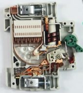
Here's the inside of a non-polarized breaker -- no magnet to pull the arc, the breaker has to be oriented vertically with the arc chute above the contacts, so they are relying upon hot air rising and the geometry of the wires may help guide the arc towards the arc chute.

1638875778222.png

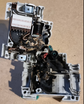
This is the same model breaker after doing an Isc measurement of 11.6A (Voc 450V) as part of commissioning. The breaker is rated for 16A at 550V. The test was done by inserting a current shunt across the lower terminals of the 2P breaker, turning it on, measuring the current with a clamp meter, and then turning the breaker off. Turning the breaker off resulted in an arc. After the arc continued for about 5 seconds and flames started coming out the top, I cut the current shunt in half using insulated wire cutters. Luckily that stopped the breaker meltdown so that things could cool down while the string was isolated on the roof.

1638875897590.png

So, what went wrong? I don't know at this point. The electrician hooked up the panels to the tops of the breakers and the inverters to the bottom. The breakers serve mainly as isolators and for lightening protection with the circuit consisting of PV Panels -> breaker -> Surge Protection Device (MOV) -> Inverter.

I'm waiting for the manufacturer to get back to me. It is a certified breaker with Australian SAA ratings and IEC 60947.2 ratings.

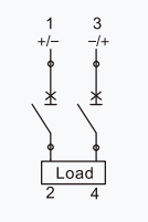
One odd thing that I did notice is that even on non-polarized breakers, manufactures still seem to indicate which side the load should be connected to, but I fail to see how this matters from an electrical standpoint. Here are two images from two different non-polarized breakers from the same manufacturer.

1638877449978.png1638877473769.png

Never a dull moment when dealing with high-voltage DC!

-Eric
 
Last edited:
Thanks for the breaker pictures!

Link to data sheet?

I don't think orientation and hot gasses rising would be fast enough to affect current interrupting. Could be cooling under steady current conditions.

I've wondered if "non-polarized" DC breakers used an electromagnet instead of permanent magnet. an alternative could be permanent magnet with arc chute on either side so arc could swing either way (would be a bit larger.)

Your undamaged breaker has what appears to be a two-turn solenoid, and the damaged one has 8-turn. That should be the magnetic fast-trip, typically 5x rated current but there is a range (trip curve A, B, C) especially for DIN rail breakers. Some breakers have thermal slow trip, and some are magnetic/hydraulic. I haven't seen the hydraulic construction, presumably a dashpot that slows travel of solenoid when force exceeds spring retention.
 
Back
Top