


You are using an out of date browser. It may not display this or other websites correctly.
You should upgrade or use an alternative browser.
You should upgrade or use an alternative browser.
Shipping Container Kitchen Mod
- Thread starter TimmehTim
- Start date
Rednecktek
Solar Wizard
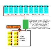
Your fuse is a little small for a 5Kw system. Go with 5000w / 48v = 104a * 85% efficiency loss = 120a * 120% overhead = 144a, round to 150a to avoid bogus annoying trips/pops. A breaker would probably be better so you can disconnect the 48v if needed.
Remember, that fuse putting power INTO the battery is the same fuse for power coming OUT OF the battery.
You're also going to want 150a Class-T fuses on each battery bank. Worst case scenario you can disconnect 1 bank and still have full wattage at half the run time while you're waiting for a replacement battery.
Might help to have a breaker for your PV if you can find a 600v DC rated 15a for servicing and troubleshooting.
Have you picked out the batteries yet and verified their BMS's/specs say they can be connected up the way you want?
Other than that it looks pretty simple and straight forward. I'm guessing you're going to feed the AC into a breaker box?
Last edited:
After posting this I read the recommended connections for the PowMr.
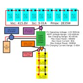
PowMr recommends a 25a DC 2-pole breaker between the panels and inverter. They recommend a 200a DC 2-pole breaker between the batteries and inverter. And they recommend using a 63a AC 2-pole breaker before the breaker box.
With respect to the Class T fuses on each string of batteries, could I use a 150a breaker instead?
I'll be using MightyMax ML4D-LI. I assumed they could be configured any way. I cant find specs on the BMS.
Attachments
Rednecktek
Solar Wizard
Seems fair if a little large on the battery breaker. I wouldn't argue with any of that other than 63a is WWAAYYY too big for a 10a array.PowMr recommends a 25a DC 2-pole breaker between the panels and inverter. They recommend a 200a DC 2-pole breaker between the batteries and inverter. And they recommend using a 63a AC 2-pole breaker before the breaker box.
The concern is that when an ANL fuse breaks, it forms a small gap between the terminals inside. With the amount of power a LFP battery can dump instantaneously that could jump that air gap and continue to feed the short/burn/whatever that was causing the problem.With respect to the Class T fuses on each string of batteries, could I use a 150a breaker instead?
Class-T and the like are rated to have a much larger air gap (respectively) and can stop that current from jumping the terminals. The fuse is there to protect the wire, not the device.
That's not going to work. According to their web page :I'll be using MightyMax ML4D-LI. I assumed they could be configured any way. I cant find specs on the BMS.
Designed to be used in parallel with a maximum of 4 identical batteries. Do not connect in series.
So, back to the drawing board with that one.
The 63amp breaker that they recommend is on the AC output side. The PV has a 25A breaker.I wouldn't argue with any of that other than 63a is WWAAYYY too big for a 10a array.
Would a Blue Sea 285 series 150A breaker be better than a fuse?The concern is that when an ANL fuse breaks, it forms a small gap between the terminals inside. With the amount of power a LFP battery can dump instantaneously that could jump that air gap and continue to feed the short/burn/whatever that was causing the problem.
Class-T and the like are rated to have a much larger air gap (respectively) and can stop that current from jumping the terminals. The fuse is there to protect the wire, not the device.
You really should get 48V batteries. So much simpler and easier than putting 4 12V batteries in series. Probably a lot cheaper too. Will has a page on these:
For a 48V LiFePO₄ battery bank you definitely want a Class T main battery fuse close to the batteries. 5000W / 48V / 85% = 122A. Use 1AWG or 1/0AWG between the batteries and inverter. The fuse should be 150A though a 200A Class T would work fine on 1AWG or larger. Using a 200A breaker could be added as well to act as a disconnect switch. Just make sure it is DC rated for at least 60VDC.
The PV breaker is only there to act as a disconnect. Make sure it is a breaker rated for at least 600VDC (or more). Any amperage over 25A is fine since it is not there to protect the wire, just act as a disconnect.
Server Rack LiFePO4 Solar Batteries
High quality, high capacity solar batteries at a great price! These are taking over the market because they have everything. State of charge indicator, communication system, high quality BMS and a...
www.mobile-solarpower.com
For a 48V LiFePO₄ battery bank you definitely want a Class T main battery fuse close to the batteries. 5000W / 48V / 85% = 122A. Use 1AWG or 1/0AWG between the batteries and inverter. The fuse should be 150A though a 200A Class T would work fine on 1AWG or larger. Using a 200A breaker could be added as well to act as a disconnect switch. Just make sure it is DC rated for at least 60VDC.
The PV breaker is only there to act as a disconnect. Make sure it is a breaker rated for at least 600VDC (or more). Any amperage over 25A is fine since it is not there to protect the wire, just act as a disconnect.
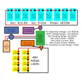
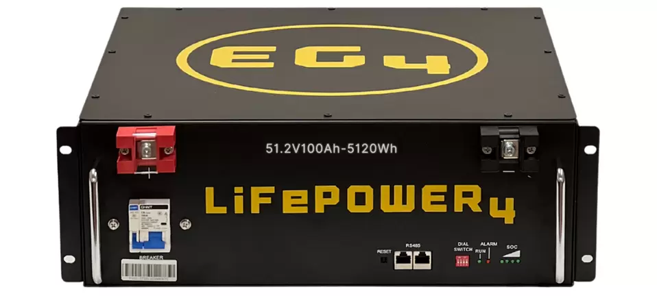
I will be purchasing 4 of the EG4 LifePower4 batteries to solve my battery issue. I've also included a 200a Class T Fuse at the battery.You really should get 48V batteries. So much simpler and easier than putting 4 12V batteries in series. Probably a lot cheaper too. Will has a page on these:
For a 48V LiFePO₄ battery bank you definitely want a Class T main battery fuse close to the batteries. 5000W / 48V / 85% = 122A. Use 1AWG or 1/0AWG between the batteries and inverter. The fuse should be 150A though a 200A Class T would work fine on 1AWG or larger. Using a 200A breaker could be added as well to act as a disconnect switch. Just make sure it is DC rated for at least 60VDC.
The PV breaker is only there to act as a disconnect. Make sure it is a breaker rated for at least 600VDC (or more). Any amperage over 25A is fine since it is not there to protect the wire, just act as a disconnect.
For the battery bank I will be using 3/0 wire as I already have a bit of it. From the battery to the inverter I will use 1/0 wire.
Attachments
Rednecktek
Solar Wizard
Ummm... you've got the batteries in series on your diagram, that's going to give you 192v to your inverter... magic smoke will be there shortly. ")
Once those are in Parallel it looks like you're good to go!
Once those are in Parallel it looks like you're good to go!
Besides putting the 4 48V batteries in parallel instead of series, I would also avoid having the main battery fuse and the inverter disconnect breaker being the same amperage. I'd use a 150A Class T fuse and then you can keep the 200A 2-pole DC breaker. At that point the breaker is only there to act as a disconnect. Also, make sure the Class T fuse and the breaker are rated for at least 60VDC. A lot of fuses and breakers can't be used on 48V system that actually get close to 60V when charging.
What is the point of the 2-pole 63A AC breaker? The AC breaker panel should have a main breaker and then a set of branch breakers. The 2-pole breaker seems redundant with the main breaker.
Your diagram only shows 2 wires for the AC side. Remember that AC has three wires, typically black, white, and green.
Rednecktek
Solar Wizard
I believe that breaker would then continue on to feed the lugs inside the breaker box rather than feeding into another breaker. If he went breaker to breaker then the 63a called for would be the one plugged into the power panel, but that would put the L1 and N lines on either leg... bad thing.What is the point of the 2-pole 63A AC breaker? The AC breaker panel should have a main breaker and then a set of branch breakers. The 2-pole breaker seems redundant with the main breaker.
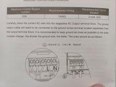
@TimmehTim IIRC that unit is a single leg of 120v power and a Neutral line. If you feed that to a standard breaker panel you'll need to install a jumper between the 2 main legs to feed both sides OR just use 1 side of the panel and ignore the other side. The Neutral wire and the Ground wire screw from the AIO will have their own bus bars inside the panel to connect to.
Does a breaker not have enough of an air gap to prevent arcing once its blown? Would a breaker alone not provide enough protection?Besides putting the 4 48V batteries in parallel instead of series, I would also avoid having the main battery fuse and the inverter disconnect breaker being the same amperage. I'd use a 150A Class T fuse and then you can keep the 200A 2-pole DC breaker. At that point the breaker is only there to act as a disconnect. Also, make sure the Class T fuse and the breaker are rated for at least 60VDC. A lot of fuses and breakers can't be used on 48V system that actually get close to 60V when charging.
I plan on using the 63a breaker as my main breaker and I will have four (4) 15amp breakers in a subpanel.What is the point of the 2-pole 63A AC breaker? The AC breaker panel should have a main breaker and then a set of branch breakers. The 2-pole breaker seems redundant with the main breaker.
Yes. The panel only provides a Live (L) and a Neutral (N) connection. The grounding line is ran separately apparently.Your diagram only shows 2 wires for the AC side. Remember that AC has three wires, typically black, white, and green.
The subpanel I have only has 1 Live leg, so this will be perfect... i think... right?I believe that breaker would then continue on to feed the lugs inside the breaker box rather than feeding into another breaker. If he went breaker to breaker then the 63a called for would be the one plugged into the power panel, but that would put the L1 and N lines on either leg... bad thing.
@TimmehTim IIRC that unit is a single leg of 120v power and a Neutral line. If you feed that to a standard breaker panel you'll need to install a jumper between the 2 main legs to feed both sides OR just use 1 side of the panel and ignore the other side. The Neutral wire and the Ground wire screw from the AIO will have their own bus bars inside the panel to connect to.
A 48V LiFePO₄ battery can push out a huge amount of current if there was a short. A Class T fuse is the best defense against that high current. With that fuse in place there is no need for the breaker at all other than if you want to use it as a disconnect.Does a breaker not have enough of an air gap to prevent arcing once its blown? Would a breaker alone not provide enough protection?
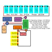
Still showing it all series-connected for the batteries. You need all the reds connected to each other and all the blacks connected to each other, not red->black.Hows this?
Are looking at the solar panels in that diagram? The diagram in post #14 shows the 48V batteries in parallel and the solar panels in series.Still showing it all series-connected for the batteries. You need all the reds connected to each other and all the blacks connected to each other, not red->black.
Doh! Misread. Sorry.Are looking at the solar panels in that diagram? The diagram in post #14 shows the 48V batteries in parallel and the solar panels in series.
Rednecktek
Solar Wizard
Really, the only important question we need answered is...
Is lunch free for those of us who helped?
Is lunch free for those of us who helped?
Similar threads
- Replies
- 60
- Views
- 4K
- Replies
- 10
- Views
- 824
- Replies
- 10
- Views
- 437
- Replies
- 4
- Views
- 379