diy solar

diy solar

Short Circuiting error with MPP 8048 MAX and SE5000 Autotransformer...

ibkickinit

New Member
Joined
Jan 25, 2021
Messages
4
Hi all,

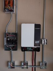
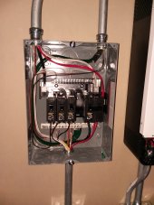
Just installed a system at my property and hitting a strange issue. I have a 48v Battery Bank, an MPP Solar 8048 MAX (230v only), and an SE-5000 Autotransformer to generate a neutral. 100-Amp Breaker Panel. 50-Amp 2-pole breaker for L1/L2 coming from the inverter into the panel, with the Inverter Ground connected to the Panel Ground Bar. Ground and Neutral Bars are bonded in the panel. The Autotransformer has L1/L2 wired to a 30-Amp 2-Pole breaker, and the Neutral connected to the Neutral Bar.

When the Inverter turns on and the breakers are off, everything is works fine. I can meter 230v at the Inverter. I turn on the Main 50-Amp breaker, nothing changes (nothing connected still). Then when I turn on the 30-Amp for the Autotransformer, the Inverter immediately throws an F05 Short Circuit error.

Tried separating the Inverter Ground from the Neutral Bar, no change. Not alot going on here, but kind of stuck. Anyone have ideas?
 
Transformer has a magnetization bias surge when first energized. You might try loading transformer with about 100 watts before turning on breaker.

If you continue to have trouble you can wire in a series NTC thermistor to limit the surge startup current.

The inverter may handle it if transformer connected before inverter activated. The inverter may softstart the transformer as inverter powers up.
 

Attachments

  • TDK inrush current thermistor.pdf
    400.7 KB · Views: 19
Last edited:
Seem to have the problem resolved posting here for future reference of others. I drew out a line diagram of the system to study and realized I had omitted the ground to the transformer. Below is the diagram as it existed, resulting in the Ground Fault condition. I disconnected the bonding between the Neutral and Ground and added a ground wire between the Ground Bar and the Autotransformer. This seems to have fixed the issue. Inverter Line Diagram-2.jpg
 
Is F05 error really mean 'Short Circuit Error' but actually is 'Ground Fault Error'? The safety ground wire is not for load current and there should be no load current on the safety ground wire, it is for fault current only and will trip the breaker.
 
I can't figure out why bonding neutral center tap of transformer to ground would cause overload fault in inverter, unless one of the inverter Line outputs was grounded.
I don't easily find the manual for it to review; they have so many models. I only see a few details in the listing.


Have you checked that all wires have correct voltage relative to each other and to ground?
With a 230V isolated inverter, you should be able to ground either line, or the center tap of a transformer.
With a source that already has one end grounded, like 230V utility line & neutral, an auto-transformer producing 115V center tap couldn't have the center-tap grounded. In that case, an autotransformer would need and extra winding and tap, for +230V, +115V, Neutral, -115V
 
Your description says you are now operating with floating neutral, unless it is grounded at transformer. You should not rely on neutral ground bonding in transformer, if it exists, and definitely not have floating neutral if transformer does not have neutral bonded to ground..

There will be voltage drop across the neutral wire from transformer with 120v loads. Ground bonding at transformer creates a voltage potential between distribution panel neutral and its ground due to 120v load voltage drop on neutral wire to transformer. That may upset load GFI's in house.

There may be some EMI filters in transformer with bypass caps from each hot leg and its case ground that may be causing the GFI problems with inverter.

You may be able to keep the distribution box ground-neutral connection but run the inverter ground to transformer case ground then ground wire from transformer case to distribution box ground.

There is another possible reason. Some autotransformers have a slightly different turns ratio on each 120vac side to make up for transformer loss. This type of autotransformer is designed to be used as a step up or step down application.

On the inverter, its GFI expects the exact same current going in and out of its hot lines. If there is a current leakage from either hot side and inverter case ground it will trip the GFI. Ground bonding of neutral from transformer may result in creating the leakage on one leg from inverter to case ground.

You really should not operate with floating neutral. It is not safe. Short of disabling inverter GFI, the only safe solution may be a true isolation transformer to keep inverter legs balance. Isolation transformers are twice the size and four times the cost of autotransformers for same VA rating.
 
I Just got my string of solar panels installed and connected this morning. Next trip, I will check continuity between Ground and Neutral of the Transformer to see if it is floating. I will also try re-bonding the Ground and Neutral if not to see if the transformer throws an error or not.
 
Post a photo of the breaker panel wiring-almost looks like you are bypassing the transformer with your 50a and 30a breakers wiring......
 
The Inverter is 230v only. No neutral. The Autotransformer takes L1 and L2 in, and creates the neutral center leg for 115v loads. This pic is from my test with a ground wire the other night. 20211103_182401.jpg
 
Post a photo of the breaker panel wiring-almost looks like you are bypassing the transformer with your 50a and 30a breakers wiring......
He is using the breaker box to provide the 240 vac to the transformer. When both 50A and 30A are on, 240vac is applied to transformer and 120 vac is brought back to panel neutral.

This is also a bad way to do it. If 30A breaker to transformer is opened there is no longer a neutral split 120 vac from transformer so any 120 vac loads in house will pull the neutral one way or other depending on which 120 vac phase side has the most loads. It is like having your neutral to grid power disconnected. Great for blowing out 120 vac devices in house, including 120 vac refrig.
 
This is also a bad way to do it. If 30A breaker to transformer is opened there is no longer a neutral split 120 vac from transformer so any 120 vac loads in house will pull the neutral one way or other depending on which 120 vac phase side has the most loads. It is like having your neutral to grid power disconnected. Great for blowing out 120 vac devices in house, including 120 vac refrig.

A way to fix that would be to gang 30A and 50A breaker together, so if balance transformer trips it shuts off inverter feed to panel.
Not sure if such breakers are easy to find for that style. There are the gang bars on pairs of poles; a gang bar across all four poles (or the two ganged sets) could do it.

Alternatively, have 50A feeding a 240 only panel, then a 30 A breaker to feed a sub-panel with this transformer and 120V loads. Connect transformer to main lugs of that panel, so it can't be switched off except by the 30A breaker which cuts power to the panel.

I've realized there are remote trip breakers (at least of the DIN rail variety, Midnight has some). I'm interested in ways to trip the breaker if a thermostat gets too hot (protection of the transformer.)
 
Hedges and RCinFLA - if you feed the inverter output into a breaker that then feeds each phase in a panel and your autotransformer is permanently connected without a breaker to the L1 L2 and N bus bars, it would prevent a flying neutral, yes? So long as the breaker feeding the panel is sized so that it can't provide power in excess of a worst-case-scenario that the autotransformer can handle without overload, then it's likely to be stable, yes?
 
Yes, if current excessive for auto-transformer disconnects power to the panel, that protects the transformer and doesn't leave system running with neutral undefined.

I think you've got an 8kW inverter and 5kW transformer, in which case you miss out on available power.
Wiring to a second panel for 240V only load would help with that.

Make sure your transformer will be adequately cooled. My idea if I set one up is a thermostatic fan, and an over-temperature thermostat which would have to trip breakers or open a relay if it is the only thing that defines neutral. (one of my potential applications it is, other is just to balance power between stacked 120V transformers.)
 
Hedges and RCinFLA - if you feed the inverter output into a breaker that then feeds each phase in a panel and your autotransformer is permanently connected without a breaker to the L1 L2 and N bus bars, it would prevent a flying neutral, yes? So long as the breaker feeding the panel is sized so that it can't provide power in excess of a worst-case-scenario that the autotransformer can handle without overload, then it's likely to be stable, yes?
Best if you have a separate small breaker box for 30 A 240vac breaker for inverter to auto transformer then feed from transformer into panel. This make the auto transformer effectively part of the inverter.

You never want to feed only 240vac into panel without a neutral. It puts all you 120vac branches at risk.

Perhaps a picture might save a few words. This is what I have right now.

If I'm not mistaken, my setup is functionally equivalent to what you described but there is no separate small breaker box - simply a breaker in the panel feeding the hot buses. The hots on the trans are connected straight to these buses and the neutral from the trans to the neutral bus in the panel.

My thinking is that if the breaker trips, all power to the panel is cut off and at that point other considerations become irrelevant.
 

Attachments

  • 001.jpg
    001.jpg
    446.3 KB · Views: 55
  • 002.jpg
    002.jpg
    529.3 KB · Views: 56
Seem to have the problem resolved posting here for future reference of others. I drew out a line diagram of the system to study and realized I had omitted the ground to the transformer. Below is the diagram as it existed, resulting in the Ground Fault condition. I disconnected the bonding between the Neutral and Ground and added a ground wire between the Ground Bar and the Autotransformer. This seems to have fixed the issue. View attachment 71278
I’ve searched for ‘SE5000 Autotransformer’ but have found nothing.

Can you provide a link to the place you purchased that Autotransformer?

Aside from the hiccups you resolved in this thread, are you happy with it?
 
fafrd: Northern AZ Wind and Sun sells them, Signature Solar, etc. About $350. I just took delivery of a Victron. More money, with higher rating, a fan, breaker, etc. And pretty blue color.....
 
fafrd: Northern AZ Wind and Sun sells them, Signature Solar, etc. About $350. I just took delivery of a Victron. More money, with higher rating, a fan, breaker, etc. And pretty blue color.....
Actually in terms of power on the neutral leg the Victron is smaller
 
Back
Top