Looks like the transformer core and windings warm up from about 16-18 watts of losses.
Meaning cooling is a concern and something like fans need to be added, or not? I’m in a basement that only very rarely exceeds 65F…
If the transformer can handle up to 25 amps continuous of mismatch, that's 3000 watts. You might be delivering 100 kilowatts down L1 and 103 kilowatts down L2 and the transformer would only run current from the difference.
Thanks for the explanation. Kind of mystifies my why it’s labeled as a 5kW Autotransformer then - does that mean when converting 120V to 240V the maximum is 5kW or 2.5kW per leg?
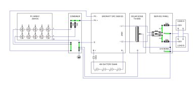
Of course, few inverters have that kind of power, but I've seen people using 2 or 3 of my growatt inverters but only 1 of these transformers. [b{So long as your loads are more or less evenly spaced you shouldn't run into problems.[/b] Growatt allows up to 6 inverters to be combined to give up to 30kw.
I’m interested in an Autotransformer for the exact opposite problem (and 3kW of maximum imbalance capacity will be more than enough).
I’m currently running 2 120V 1kW GTIL inverters, one per leg, for load-shaving (offsetting consumption).
One of the big attractions of the GTILs is they just plug in like any appliance (a toaster oven that pushes some power into the socket rather than sucking some out) so no modification to existing wiring is needed (though I did add a new dedicated two-phase breaker wired to a new dedicated 2-phase outlet).
Everything works like a charm but I’ll often have one GTIL inverter maxed out at 800W (they only have 80% efficiency) while the other is putting out under 30W.
So first, I’ve obviously got some serious imbalance during the typical nighttime usage when it’s mainly fridges consuming, and second, I’m often underutilizing my total inverter capacity and leaving some serious self-consumption I could be offsetting on the table (over 45%).
So I’ve been thinking about tracking all the loads involved down and swapping legs on those circuits to better balance my load, but what a huge PITA.
So I’m considering wiring one of these 5kW (25A) Autotransformers into a dedicated circuit just to more easily balance load to ‘unlock’ the additional ~45% power capacity of my underutilized GTIL.
The imbalance I can often see is under 800W / 6.7A but because the one inverter is maxed out, it is masking whatever additional imbalance may reside beyond that level. But if a 20A breaker protecting the Autotransformer trips, I know I’ve got some big loads I need to track down and redistribute.
I’m on the fence as to whether spending ~$350 to avoid swapping a bunch of circuit breakers around makes sense, but the Autotransformer is more universal (always rebalancing, no matter which loads) and as a bonus it will guarantee that my 2 GTIL inverters are also always balanced in terms of output - that will reduce noise from cooling fans while also probably extending the lifetime of the overutilized unit.
Plus, if/when I add more inverter capacity in the future, I can consider going 240V single-phase…
A new question that comes to my mind is - what do you do if you think you're going to often have unbalanced loads on your phases and are likely to go well outside the 25A current capacity of the transformer? Can more than one of them be "paralleled" to give you 50, 75... amps?
I would think multiple Autotransformers on multiple dedicated 20A or 25A two-pole circuits should work in parallel to add balance capacity just fine…. Each has their own neutral being run from the main panel, right?
I've looked for larger transformers like this but the only results I find are for industrial use; they're huge, heavy, and expensive.
I’m looking for lower capacity / cheaper Autotransformers but I don’t think something like this 3kW 240/120V step-transformer Amazon sells as an ‘Autotransformer’ is the same thing, right?


 diysolarforum.com