diy solar

diy solar

Show off the appliances, hacks, gadgets, solutions, and habits that have saved you energy!

Dzl

Unofficial Forum Librarian & Perpetual Newbie
Staff member
Moderator
Joined
Dec 10, 2019
Messages
5,108
Location
West of the rockies
I'm hoping to start a general show and tell and discussion thread on the things you have done, bought, invented, and hacked, to improve efficiency.

What made the biggest different? What unique things have you done?
 
My generation doesn't care for the word 'Hack' or 'Hacked'...
Denotes someone taking shortcuts or doing things in a generally sloppy manner.

Examples,
"That Guy Is A Hack" or "This is a real hack job, we'll have to start from scratch".

Electrical induction silver soldering.
Completely closes up air spaces, 100% electrical conduction potential of any given connection.
If you can get it into the inductor field, and electrical soldering or silver soldering (much higher temps) won't damage insulation or components, you can get the maximum current carrying potential out of connections.

Full on silver soldering will often tear away base material when the mechanical limits of the joint are reached.
Copper will often fail on large conductors before the silver solder fails.

For big, heavy duty battery lugs on big wire, it makes electrical soldering MUCH faster & easier, the wire/insulation doesn't heat up nearly as quickly since the energy is concentrated in the terminal end and doesn't have nearly as much time to conduct up the wire strands.

---------------------------------

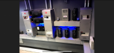
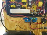
Big, Heavy no BS contactors for high amp batteries, both over and under voltage opening of the circuit so LFP batteries stay within charge tolerance.
Doesn't matter if charge controller or BMS fails, redundant system to take the battery out of Bank until the issue is solved.
 
Based on advice from this forum, I "hacked" the inverter switch so I can utilize the Victron battery connect low voltage shutoff. Tested and works great. It's the little red wire going into the back of the inverter, it's connected to the switch lead that powered the inverter on. After this photo was taken, I buttoned everything back up and added circuit protection for the 12v inverter wire and the 24v-to 12v converter not shown.
 

Attachments

  • 20200209_111755.jpg
    20200209_111755.jpg
    86.4 KB · Views: 20
Based on advice from this forum, I "hacked" the inverter switch so I can utilize the Victron battery connect low voltage shutoff. Tested and works great. It's the little red wire going into the back of the inverter, it's connected to the switch lead that powered the inverter on. After this photo was taken, I buttoned everything back up and added circuit protection for the 12v inverter wire and the 24v-to 12v converter not shown.

Thanks for using the word "hacked" in the proper context.
 
Based on advice from this forum, I "hacked" the inverter switch so I can utilize the Victron battery connect low voltage shutoff. Tested and works great. It's the little red wire going into the back of the inverter, it's connected to the switch lead that powered the inverter on. After this photo was taken, I buttoned everything back up and added circuit protection for the 12v inverter wire and the 24v-to 12v converter not shown.

Is that disconnect programmable for voltage?

With LFP 1/10 volt matters and that is way too often a 2 or 3 step process.
I've been doing a low voltage sensor that has fine enough adjustment, intermediate (higher amperage) 'kicker' relay, and a big amp contactor.
If you decide what the cutoff voltage is, that would make it stupid simple, and correct application for that low battery disconnect since it's single direction use.

I'd say all in all, it's not 'Hacked' one bit,
It's thought through, protected, correctly connected and correct application.
Good Job! (y)
 
The thread is about hacks you have used.... But I will show an idea I have not tried yet.

I like the Chargery BMS but I do not like the power draw of the required relays. I came up with this idea for using a Magnetic Latching By-stable relay. This is a relay that uses a momentary positive pulse to turn on and a momentary negative pulse to turn off. Here is a 100 amp version of one:
https://www.ebay.com/itm/333442060231

1581291384936.png
Notes:
  • The circuit shown is for a 12 Volt system. A 24volt system would need different relays for Relay 2 & 3)
  • The weidmuller 127150000 relays are DIN mount solid state 2 amp relays. The 'coils' only require about 10mA.
  • The zenor diodes form a bi-directional snubbing circuit for the relay2 coil

Turn On sequence
  1. The circuit as shown is the starting point with everything off.
    Note that in this state,
    • both sides of relay 2 are hooked to the positive, so nothing will happen.
    • The load line is not energized so relay 3 is not energized.
  2. The chargery energizes the signal, causing relay 1 to turn on, grounding the S side of relay 2.
  3. Relay two now has an energized coil with Positive on the I terminal so it turns on, energizing the load and relay 3
  4. Relay 3 is now turned on, so the I side of relay 2 is now at ground.
  5. Since both sides of relay 2 is connected to negative, the coil is de-energized, but since it is a bi-stable relay, it does not change.
At this point relay two is on but not drawing any current on the coil, The two Weidmuller relays are on but only drawing about 20mA.

Turn off sequence
  1. The initial condition is that both of the Weidmuller relays are on and the bi-stable relay is on but the coil is not energized.
  2. the Chargery turns off the relay signal so relay 1 switches state, connecting the S side of relay 2 to positive.
  3. Relay two now has an energized coil with Positive on the S terminal so it turns off, de-energizing the load and de-energizing relay 3
  4. Relay 3 now turns off, so the I side of relay 2 is now at Positive so the coil is de-energized but since it is a bi-stable relay, it does not change.

I have not tried this because I need a 24 volt 200 amp bi-stable latching relay and so far I have not found an affordable one. I am in contact with several aliexpress vendors about sourcing one but with the outbreak... communications have ceased.

I am hoping to find a 200 amp bi-stable latching relay with auxiliary contacts. Then I could do this circuit:
1581290915764.png
This is essentially the same circuit but relay 2 & 3 are combined
 
Last edited:
Very nice relay logic, I didn't saw any error, it should work no problem ;)
 
This is a custom Outback power IBR3 that I built, it has a independent Flexnet, hub and mate installed that monitors all three rows of Simpliphi batteries independently, this is then aggregated in optics with the master Mate 3. This ultimately gives me 6 channels of monitoring and allows me to make sure the batteries are staying somewhat balanced.
 

Attachments

  • F1FC1658-E86C-4219-8850-1C0D58641183.jpeg
    F1FC1658-E86C-4219-8850-1C0D58641183.jpeg
    88.4 KB · Views: 33
  • F797DF46-E8CF-4011-9326-F175642B4EB9.jpeg
    F797DF46-E8CF-4011-9326-F175642B4EB9.jpeg
    82.5 KB · Views: 32
  • Like
Reactions: Dzl
@JeepHammer

In this context, I'm using hack to mean something along the line of 'creative and/or unorthodox or innovative problem solving, modification, or repurposing, generally beyond or outside the scope of what the component or system was originally designed for.'

Sometimes it might be a straight up 'hack job', but other times it might be an exceptionally elegant and innovative solution. In this thread, hack should not be interpreted in a negative light (though it should be differentiated from 'engineered')
 
7005-d1488f427fcd0ae5ff89f04491a008d3.jpg

This looks cool AF, a room straight out of a James Bond movie :D
 
This looks cool AF, a room straight out of a James Bond movie :D
Thanks I enjoy building power rooms and have some really cool ones out there! Here’s another view of it
 
Nice!! Mixing art and engineering!
It’s one of the things that’s always kept me busy as an installer and helped me with manufacturer traction. I’m new to this form and won’t blow you guys up, but I have some neat installs out there that most of you will dig
 

Attachments

  • 2D5B6B88-E3A9-437C-8681-2B9B744BB725.png
    2D5B6B88-E3A9-437C-8681-2B9B744BB725.png
    248.4 KB · Views: 24
This is a custom Outback power IBR3 that I built, it has a independent Flexnet, hub and mate installed that monitors all three rows of Simpliphi batteries independently, this is then aggregated in optics with the master Mate 3. This ultimately gives me 6 channels of monitoring and allows me to make sure the batteries are staying somewhat balanced.
love it...used to think i wanted a 'man shed', now i just want a room like yours....lol.
 
It’s one of the things that’s always kept me busy as an installer and helped me with manufacturer traction. I’m new to this form and won’t blow you guys up, but I have some neat installs out there that most of you will dig
RE Power rooms of the rich and famous!
Love it. Great stuff. There are mind blowing installs out there, but most will never see them, quite private.

Amazing what can be done with a little flexibility in budget and somebody with skill and care.

Truly impressed with your talent and amazing clients who would be able to commission a work like that!

Alittle to casino royale james bond villian for my taste...... ok, i want one!
 
Last edited:
RE Power rooms of the rich and famous!
Love it. Great stuff. There are mind blowing installs out there, but most will never see them, quite private.

Amazing what can be done with a little flexibility in budget and somebody with skill and care.

Truly impressed with your talent and amazing clients who would be able to commission a work like that!

Alittle to casino royale james bond villian for my taste...... ok, i want one!

I want one also... Something with flip over tool racks and self cleaning workbenches!
 
I want one also... Something with flip over tool racks and self cleaning workbenches!
Lol I haven’t figured out the self cleaning part but my cat tries to help me out most of the time. I experimented with some Formica last year and built a pretty cool multi use work bench though it’s cantilevered off the wall using compression for the top
 

Attachments

  • CD1A8743-C91D-4AE6-B230-E34A83EC61B6.jpeg
    CD1A8743-C91D-4AE6-B230-E34A83EC61B6.jpeg
    79 KB · Views: 19
  • C4A30F84-FE75-4659-A9E6-51780BDE1CBB.jpeg
    C4A30F84-FE75-4659-A9E6-51780BDE1CBB.jpeg
    78.7 KB · Views: 19
  • A1C3983B-E83A-4477-B137-E685A5156C89.jpeg
    A1C3983B-E83A-4477-B137-E685A5156C89.jpeg
    144.1 KB · Views: 17
Back
Top