diy solar

diy solar

Shunt between the battery and the BMS?

harpo

Good at many things, master of none
Joined
Oct 1, 2019
Messages
98
Location
PA, FL
I have been reading on this forum and watching Off Grid Garage and, of course, Will Prowse YouTube channels among others. There seems to be no clear cut answer to my question: shunt between battery and BMS or BMS between battery and shunt? There are good reasons on both sides of this issue.
From what I read evidently Victron wants their shunt between the battery and the BMS but I have not confirmed this for myself yet. I am using a Victron Smart Shunt.
Others think that the BMS should be the first thing off the battery and then everything else including the shunt. I am wondering if it makes a whole hill of beans which one you use because there are so many on both sides of this issue. Care to comment?
 
I put the shunt before the bms like this.
battery sub_assembly
That way the breaker can be opened and the bms can trip and battery monitor won't loose track of the state of charge.
Extra care should be taken to not let the battery monitor drain the battery.
 
Last edited:
Will the Smart Shunt and/or the BMS have a parasitic draw? I need to leave my system dormant (no charging and no loads) for up to 4 months. I don't want ANY parasitic draw on the battery when I prepare the system for hibernation.
 
Will the Smart Shunt and/or the BMS have a parasitic draw? I need to leave my system dormant (no charging and no loads) for up to 4 months. I don't want ANY parasitic draw on the battery when I prepare the system for hibernation.
Both the bms and the shunt have a small parasitic draw.
Check the doco for your devices but I guess it will be ~10-20 milli amps per device.
 
. I don't want ANY parasitic draw on the battery when I prepare the system for hibernation.
Smart Shunt draws less than 1mA.

My policy is to install the shunt after the BMS, and with a ready built battery you have no option. I don't expect the BMS to trip unless there are serious problems with the system.
Even the Victron Smart shunt will accumulate errors and will need a manual sync to 100% every so often.

Mike
 
My shunt doesn't draw power from the negative battery cable. It has a separate, fused, positive connection. That can be switched off.
As I don't run my inverter negative through the BMS, my shunt is between the battery negative and the BMS plus inverter negative connections.
 
My shunt doesn't draw power from the negative battery cable. It has a separate, fused, positive connection. That can be switched off.
As I don't run my inverter negative through the BMS, my shunt is between the battery negative and the BMS plus inverter negative connections.
So, if I understand it here is the order of connections on the negative side of things: Battery negative------shunt (negative inverter cable connected to the shunt) and then the BMS. I think I have this right but how you worded your entry "....plus the inverter negative connections" had me a bit confused.
As long as the inverter negative cable is on the far shunt terminal, the shunt will be able to assess or "count" the current coming out of the battery when the inverter is in use but the BMS will not. So, the SOC from the shunt will be accurate but if the BMS has a data pid for SOC it will not be accurate.
Do I have this correct?
I have confirmed the Victron Smart Shunt draws less than 1 mA so I am not too concerned about that. What I can't seem to find is if the BMS draws any current when there are no loads on the battery and, if so, how much. This will have implications for my 4-5 months of no-use storage of the battery when no one will be visiting or using the cabin. If I unhook both the BMS and the shunt when in storage, all the data from the battery such as SOC will be lost.
 
I have confirmed the Victron Smart Shunt draws less than 1 mA so I am not too concerned about that. What I can't seem to find is if the BMS draws any current when there are no loads on the battery and, if so, how much.
The bms does draw power.
The cell monitoring takes some power.
The draw will be in the same ballpark as the shunt, more when balancing of course.
In sensible setups balancing only occurs while charging though.

If the inverter bypasses the bms then it should be controlled by the bms using external switching.
 
My system is designed so the BMS will not disconnect the battery except in a fail safe last ditch emergency. The solar CC is custom programed for proper charge parameters that protect the battery. The inverter has a LV control circuit that first switches off the load then shuts down the inverter. I can't trust these inexpensive BMS circuits to behave with higher amperes, despite their "rating". The battery also has a low voltage disconnect that opens all other drains. In a fail-safe condition, all the control circuits shut down as well. So the inverter will shut down during fail-safe. This can be a problem as shutting down an inverter under load can be bad for the inverter. Read your manual.
I have a shunt based battery monitor and do not need any BMS guess SOC. My bet is the BMS SOC is not accurate anyway.
 
Last edited:
The shunt will not measure the battery self discharge nomatter where its positioned. I suggest leaving the battery in storage mode with everything disconnected. Its no big deal to charge up again and reset the Smart Shunt to 100% when the battery is put back Into commission.

Mike
 
So, if I understand it here is the order of connections on the negative side of things: Battery negative------shunt (negative inverter cable connected to the shunt) and then the BMS. I think I have this right but how you worded your entry "....plus the inverter negative connections" had me a bit confused.
As long as the inverter negative cable is on the far shunt terminal, the shunt will be able to assess or "count" the current coming out of the battery when the inverter is in use but the BMS will not. So, the SOC from the shunt will be accurate but if the BMS has a data pid for SOC it will not be accurate.
Do I have this correct?
I have confirmed the Victron Smart Shunt draws less than 1 mA so I am not too concerned about that. What I can't seem to find is if the BMS draws any current when there are no loads on the battery and, if so, how much. This will have implications for my 4-5 months of no-use storage of the battery when no one will be visiting or using the cabin. If I unhook both the BMS and the shunt when in storage, all the data from the battery such as SOC will be lost.
That's what I'm doing. I do protect the battery from the inverter through the BMS though. I use the strategy Will laid out in this video.

 
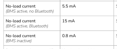
BMS drain is not that much... here is the specs on a JBD 100A unit which means it will drain a 100Ah battery in:

BMS on, WITH bluetooth active===>100Ah / 0.015A = 6666 hours or about 9 months from a full charge
BMS on, NO bluetooth ===>100Ah/ 0.0055 or about 2years!!


1636821680576.png
 
Like I posted. My quality Samlex inverter states in the warnings "Do not switch off while under load" Will's circuit does shut down the inverter if the BMS trips. Will simplifies a complicated problem. Don't rely on the BMS to control your system.
 
BMS drain is not that much... here is the specs on a JBD 100A unit which means it will drain a 100Ah battery in:

BMS on, WITH bluetooth active===>100Ah / 0.015A = 6666 hours or about 9 months from a full charge
BMS on, NO bluetooth ===>100Ah/ 0.0055 or about 2years!!


View attachment 72185
Good information! Where did you get this information? I ordered a 200a JBD BMS and would like to know these numbers.
 
Like I posted. My quality Samlex inverter states in the warnings "Do not switch off while under load" Will's circuit does shut down the inverter if the BMS trips. Will simplifies a complicated problem. Don't rely on the BMS to control your system.
I'm not relying on the BMS to control my system. I'm using the BMS as a Fail-Safe in case the programming in my inverter fails to perform. My inverter is set up to shut down well before the low voltage disconnect on the BMS trips.

My inverter also features a remote disconnect feature. It is far less crude than the specific method Will used in his video. I'm using that to connect to the shutdown signal. If it receives the signal to shut down, in other words the BMS turns it off, the inverter should manage that gracefully.
 
My shunt is after the bms.

My logic is the bms and shunt power draw is unnecessary and if the bms cuts off on the low end I don't want to add even more draw to it.


In reality I don't think it matters much. The power drawn is minimal either way and you probably shouldn't leave it unattended long enough for a few mA to matter significantly.
 
Back
Top