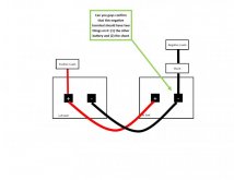
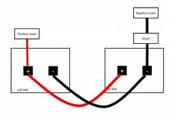
I just have to address a few things I have read here, if I can remember them. Photo of shunt in #69; There are too many wires on the battery side. Are you sure you labeled it correct? Should only be one wire connecting shunt to negative battery. 105c wire; Using a voltage drop table for the AWG and ampacity table for the fuse. The cable should never get close to warm. Unless there is a short and that is why we use fuses. Running wire from the battery negative to the battery side of shunt. Properly sized. Same with the load side of the shunt. Run wire shunt to negative battery side of buss bar, or just to the original negative battery wires.


")