diy solar

diy solar

Shunt question

smorgan345

New Member
Joined
Jun 24, 2021
Messages
23
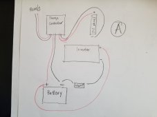
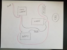
I'm trying to wire up my system and I thought I had it figured out until I tried to integrate a shunt with battery monitor. So this is probably a couple of questions. I have attached two diagrams. 'A' is what I was originally planning to do and then I read the shunt can't have anything between it and the battery so 'B' is what I was thinking now because I figured in 'A' the shunt wouldn't be picking up the DC panel loads?. I thought I saw where it looked like Will wired the DC fuse panel to the terminals on his inverter? For some reason I was thinking that this would send too much power to the DC panel. Do the load terminals on the charge controller regulate the power in some way? Also does the negative wire from the charge controller need to be on the load side of the shunt like in 'B' or should it connect directly to the Neg. terminal on the battery? Sorry I have a very limited understanding of this stuff. Thanks for any input.
 

Attachments

  • A.jpg
    A.jpg
    80.2 KB · Views: 60
  • B.jpg
    B.jpg
    95.5 KB · Views: 61
I thought I saw where it looked like Will wired the DC fuse panel to the terminals on his inverter?
If he did.... it was because it was a convenient place to connect.

Do the load terminals on the charge controller regulate the power in some way?
I have never used the load terminals on a charge controller.... but I do think some of them will disconnect the load if the DC voltage gets too load. (check the manual) BTW: The load terminals on controllers are typically limited to pretty small loads.

Also does the negative wire from the charge controller need to be on the load side of the shunt like in 'B' or should it connect directly to the Neg. terminal on the battery?
Yes. The negative from the controller should be on the load side like in B. The way the shunt is shown in A, the only current measured would be the current going to the inverter. It would not 'see' the current from the charge controller.

The only issue I see with B is that there is no low voltage disconnect for the DC loads.
 
If he did.... it was because it was a convenient place to connect.


I have never used the load terminals on a charge controller.... but I do think some of them will disconnect the load if the DC voltage gets too load. (check the manual) BTW: The load terminals on controllers are typically limited to pretty small loads.


Yes. The negative from the controller should be on the load side like in B. The way the shunt is shown in A, the only current measured would be the current going to the inverter. It would not 'see' the current from the charge controller.

The only issue I see with B is that there is no low voltage disconnect for the DC loads.
Thank you! So would a low voltage disconnect be something like a connector of some sort on the wires that go from the DC fuse panel to the inverter terminals so that it could be disconnected if needed? And just to verify, connecting the DC fuse panel to the inverter terminals won't burn up the DC appliances? Right now all that will be hooked to the DC panel are some low voltage lighting strips and a usb charging port. Thanks again.
 
So would a low voltage disconnect be something like a connector of some sort on the wires that go from the DC fuse panel to the inverter terminals so that it could be disconnected if needed?
A low voltage disconnect is something like the Victron Battery protect. (The victron is the one I use, but I believe there are lower cost ones out there.
And just to verify, connecting the DC fuse panel to the inverter terminals won't burn up the DC appliances?
Let's be very clear: Connecting the DC Fuse panel to the DC BATTERY INPUT terminals of the inverter would not damage the DC devices.
However, Connecting the DC Fuse panel to the AC terminals of the inverter would definitely smoke the DC devices.

Personally, I would avoid connecting the DC Fuse Box to the DC BATTERY INPUT terminals of the inverter. That is called daisy chaining and in general, is not a good idea.

Instead, I would take the positive of the battery to a Bus bar and the load side of the shunt to another busbar and then hook everything to the busbar.

Also, we have not discussed fusing yet.... there needs to be proper fusing in the circuit.

1636223694312.png
 
A low voltage disconnect is something like the Victron Battery protect. (The victron is the one I use, but I believe there are lower cost ones out there.

Let's be very clear: Connecting the DC Fuse panel to the DC BATTERY INPUT terminals of the inverter would not damage the DC devices.
However, Connecting the DC Fuse panel to the AC terminals of the inverter would definitely smoke the DC devices.

Personally, I would avoid connecting the DC Fuse Box to the DC BATTERY INPUT terminals of the inverter. That is called daisy chaining and in general, is not a good idea.

Instead, I would take the positive of the battery to a Bus bar and the load side of the shunt to another busbar and then hook everything to the busbar.

Also, we have not discussed fusing yet.... there needs to be proper fusing in the circuit.

View attachment 71534
yes this looks much more organized. I will have to get some Bus Bars I guess. Can you tell me what the Battery Protect does? This is the first I've heard of those. I have fuses for all of my positive wires except for the one that goes from the shunt to the bus bar. The directions didnt specify one but do you think I should have one? If so what size? The wire is 14 awg so maybe 5 amp? One last thing, is the blue circle connected to the shunt a ground? If so where is the ground on the shunt? I'm attaching a pic, is it the screws on the front? Thanks.
 

Attachments

  • shunt.jpg
    shunt.jpg
    84.1 KB · Views: 14
Can you tell me what the Battery Protect does?
I have a battery protect in my system. Essentially it is there to ensure your DC loads don't over discharge the battery. The battery protect is effectively a smart switch. If it detects the battery voltage drops below some programmed value then it will open its switch thereby turning off your DC loads. When the battery voltage gets higher again it will close its switch again and allow power to your DC loads again.

It can handle other related tasks as well but that's its primary usage. You can see more about Victron's battery protect at:

 
I also use a Victron battery protect for my dc loads directly and to control my inverter via external switching.
 
I have a battery protect in my system. Essentially it is there to ensure your DC loads don't over discharge the battery. The battery protect is effectively a smart switch. If it detects the battery voltage drops below some programmed value then it will open its switch thereby turning off your DC loads. When the battery voltage gets higher again it will close its switch again and allow power to your DC loads again.

It can handle other related tasks as well but that's its primary usage. You can see more about Victron's battery protect at:

I am using a Renogy Rover 60 amp MPPT Charge Controller and it has some app and wifi unit on it. I think I read that it will shut down if the battery gets too low. Would that be kind of the same thing?
 
The main purpose of a charge controller is of course to charge the battery but it also gets some power from the battery. I suppose if there is no solar input and the charge controller sees the battery is too low it might shut itself down. But that doesn't do anything for all of your DC loads connected to your DC fuse box. The battery protect is typically for your DC loads. So what you describe is kind of similar in nature but not in use. As a further example my inverter will shut itself down if the battery is too low. In my case I set this at a much higher voltage than the battery protect because I have more important things connected via DC. So I want my AC load (from the inverter) to be shutdown to save power for the important DC loads. But even those will get shutdown by the battery protect eventually if the battery gets even lower.
 
I have fuses for all of my positive wires except for the one that goes from the shunt to the bus bar. The directions didnt specify one but do you think I should have one?
Yes. Anything coming off the positive Busbar should have a fuse. Anything from 1A to 5 A is fine.
 
I am using a Renogy Rover 60 amp MPPT Charge Controller and it has some app and wifi unit on it. I think I read that it will shut down if the battery gets too low. Would that be kind of the same thing?
If the loads are hooked via the load output of the charge controller, then yes. However, in the diagram above the loads are not hooked to the charge controller so the shunt can 'see' the load current.
 
FilterGuy 's wire diagram is good. I use Blue Sea Busbar with fuses on the positive BusBar. I recommend another fuse for the inverter. While the fuse at the battery will protect that wire, my best-practices has a catastrophic fuse at the battery with a smaller fuse at the positive BusBar for the wire to the inverter. That way if the inverter circuit fucks up the whole system doesn't shit out.
I also want to know what the extra attachment on FilterGuy shunt. The one with the blue circle.
 
If the loads are hooked via the load output of the charge controller, then yes. However, in the diagram above the loads are not hooked to the charge controller so the shunt can 'see' the load current.
Got it. Thank you I really appreciate your help.
 
I also want to know what the extra attachment on FilterGuy shunt. The one with the blue circle.
It is whatever meter is displaying the SOC. The OP did not specify what was reading the shunt but I assume there is some type of meter at the end of the black cable in the diagram

1636306691590.png

I recommend another fuse for the inverter. While the fuse at the battery will protect that wire, my best-practices has a catastrophic fuse at the battery with a smaller fuse at the positive BusBar for the wire to the inverter. That way if the inverter circuit fucks up the whole system doesn't shit out.
I go back and forth on the extra fuse. Either way can be made safe.
 
So do you leave the shunt in the permanently? It is a resistor, right? Wouldn't' it decease efficiency?
 
That negligible loss presents us with so much useful knowledge about the battery. Priceless.
 
Back
Top