diy solar

diy solar

Signature Solar EG4 6.5K Off-Grid Inverter | 6500EX-48

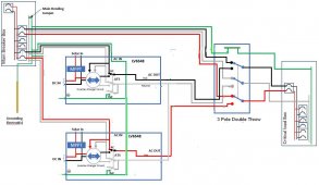
Folks, I put together drawings showing the grounding and bonding of the MPP LV6548 and EG4 6500EX-48 for several different scenarios.

Please let me know if you see any errors.
@FilterGuy I'm reviewing this document and the one option i don't see anywhere in there is a split phase setup with two (or more) EG4 6.5kw, Grid Power In, and no critical load panel. Functionally, the configuration i mention is the same as 8A or 8B but using grid instead of a generator, and substituting the main panel for the critical load panel. But I'm sure there is more to it than that. I'm trying to figure up how to do 2 EG4 6.5EX, split phase, 16KW array, ~30Kwh of battery backup, and grid power supplement for charging batteries or making up load when PV array output is too low.
 
Yes, this inverter works with Solar assistant via the USB cable. I only have 1 inverter and 1 eg4 battery. I prefer the inverter in USE mode with the console cable from the battery to the raspberry pi. after hooking up the console cable to the battery it seems that it pulls more data etc ( straight from the BMS vs reading what the inverter thinks) . I think this is the ideal setup assuming Solar Assistant plays well with multiple inverters but i have not tried that yet. Once you turn on the MQTT discover i think Home Assistant finds 32 metrics or so.

I can screenshot every page in solar assistant and post here if there's interest in that. Solar assistant is very easy to install and configure. If the raspberry pi has a connection to the internet you are able to monitor remotely. I don't like that you cant log into the raspberry pi, the only access you get is the web interface for updates and setting up Wifi. I guess thats understandable to make it harder to pirate the software or prevent people from breaking the software etc.

Overall Solar assistant to inverter via usb and solar assistant console cable to battery i think is the ideal setup ( assuming it handles multiple inverters/batteries). I guess the fault 61 was a blessing in disguise as i probably wouldn't have explored solar assistant otherwise. I have a Power over ethernet adapter to power the raspberry pi (cat 5) so it makes it simple to mount/run cable. There's 48v dc to USB to power the pi from the bus bars as well. Depending on which pi you have you could use wireless or hardwired ethernet. I prefer to hard wire anything i can.

My goal with Solar Assistant is to charge my EV with excess solar once the solar battery is full. I dont drive a ton but i've managed to only charge via solar for the last month or so. With Home assistant i should be able to send power to my car and adjust the charging amps to match solar output or rather adjust the amps as to not draw from the battery when the sun is out. once you get the data into home assistant the sky is the limit. i plan to setup voice announcements with solar generation, battery percentage etc etc.

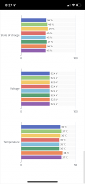
View attachment 104343

Home Assistant output.


View attachment 104344
View attachment 104345

More solar assistant screenshots

View attachment 104346

View attachment 104348


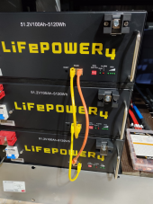
I just got my Solar Assistant in the mail today and hooked it up. I got it communicating with one battery at a time (EG4 Lifepower with no LCD), but I wasn't able to get it working with all of them at once - not yet anyhow). I only tried using network patch cables to daisy chain between the batteries, so I'm guessing it's the wrong pinout or something - need to research it a bit more.

When attempting to use USB Direct or USB to RS232, I couldn't get it working with either - the difference is that I have two of them set up in a split phase configuration, so I'm not sure if some additional step needs to be taken?

Has anyone else made it work with multiple inverters in a split phase configuration?

UPDATE: It was just a bad Micro-USB cable.... or maybe one that just did power and not data - not sure. It's now reading the inverter data via USB Direct.

The only issue that I'm seeing is that it only appears to be gathering some data from the second inverter... still investigating.

Does anyone know what I need to do to get it working with multiple batteries? Guessing it's something to do with the cables.

Thanks,
Eric
 
Last edited:
Does anyone know what I need to do to get it working with multiple batteries? Guessing it's something to do with the cables.

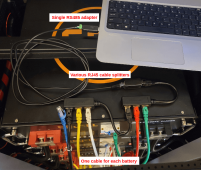
You have to use something to put them together. I use a combiner 1/3 connector. These are communicating via rs485. Use a dumb switch:hub or a few of these.

Ethernet Extender - RJ45 Ethernet... search Amazon.

This is what I have for now as a solution.
 
You have to use something to put them together. I use a combiner 1/3 connector. These are communicating via rs485. Use a dumb switch:hub or a few of these.

Ethernet Extender - RJ45 Ethernet... search Amazon.

This is what I have for now as a solution.

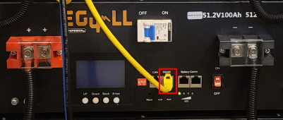
My understanding was that I'd only need a hub if I had one of the EG4 batteries that just had a single RS485 port, as they describe in their help section: https://solar-assistant.io/help/battery/eg4

Mine has two RS485 ports per battery, so I was going to wire them similar to this - one battery to the next to the next, etc:

1659575670047.png


I plugged the USB to RS485 cable into the top battery starting with a dip switch setting of 2, then the next battery was 3, and so on until I had the sixth battery set to 7. I thought that would essentially be the same thing as a hub.
 
My understanding was that I'd only need a hub if I had one of the EG4 batteries that just had a single RS485 port, as they describe in their help section: https://solar-assistant.io/help/battery/eg4

Mine has two RS485 ports per battery, so I was going to wire them similar to this - one battery to the next to the next, etc:

View attachment 105351


I plugged the USB to RS485 cable into the top battery starting with a dip switch setting of 2, then the next battery was 3, and so on until I had the sixth battery set to 7. I thought that would essentially be the same thing as a hub.
I have 8 “pro’s” in total. You will have to put them all into a hub, and follow the how to in the help area you are describing.

You have to with all of these batteries as they do not cross communicate with rs485. I thought the same as well, but it does not fiction this way.
 

Attachments

  • B24A304A-C24A-448D-ADB5-FCF50FABC946.png
    B24A304A-C24A-448D-ADB5-FCF50FABC946.png
    171.7 KB · Views: 23
@FilterGuy I'm reviewing this document and the one option i don't see anywhere in there is a split phase setup with two (or more) EG4 6.5kw, Grid Power In, and no critical load panel. Functionally, the configuration i mention is the same as 8A or 8B but using grid instead of a generator, and substituting the main panel for the critical load panel. But I'm sure there is more to it than that. I'm trying to figure up how to do 2 EG4 6.5EX, split phase, 16KW array, ~30Kwh of battery backup, and grid power supplement for charging batteries or making up load when PV array output is too low.
I am not following what you are trying to do. (I assume you have seen 6A and 6B but those are not what you want)
 
My understanding was that I'd only need a hub if I had one of the EG4 batteries that just had a single RS485 port, as they describe in their help section: https://solar-assistant.io/help/battery/eg4

Mine has two RS485 ports per battery, so I was going to wire them similar to this - one battery to the next to the next, etc:

View attachment 105351


I plugged the USB to RS485 cable into the top battery starting with a dip switch setting of 2, then the next battery was 3, and so on until I had the sixth battery set to 7. I thought that would essentially be the same thing as a hub.
I have this LifePOWER4 version of the EG4 batteries communicating with Solar Assistant, I connected multiple batteries just like your picture shows. I would guess your dip switch setting is not correct, remember after changing the dip switch, you need to power cycle the battery for the new dip switch setting to take effect.

Solar Assistant has the following note: on their EG4 Page.
"Some users reported the dip switches in their EG4 battery manual are the wrong way around. If you are having trouble reading your battery, consider ON might be OFF and/or the first dip switch might be the last."
 

Attachments

  • EG4 and SolarAssistant setup - Trouble Shooting.jpg
    EG4 and SolarAssistant setup - Trouble Shooting.jpg
    10.4 KB · Views: 8
I have this LifePOWER4 version of the EG4 batteries communicating with Solar Assistant, I connected multiple batteries just like your picture shows. I would guess your dip switch setting is not correct, remember after changing the dip switch, you need to power cycle the battery for the new dip switch setting to take effect.

Solar Assistant has the following note: on their EG4 Page.
"Some users reported the dip switches in their EG4 battery manual are the wrong way around. If you are having trouble reading your battery, consider ON might be OFF and/or the first dip switch might be the last."
How many batteries do you have, and how many are communicating/showing up in Solar Assistant?
I can clean mine up if this is supposed to work as stated. I did try daisy chaining these together as you have discussed, it did not work for me. So I had to go the Hub route as I stated previously.

These images below are how I have mine connected, one cable per battery hooked into a 1/3 combiner/hub. This is from https://solar-assistant.io/help/battery/eg4 as you indicated. In this image you can see he did not daisy chain these connections but put them into a series using the hub. Im curious if what you have will work for me.

Sorry we are hijacking this thread. This should be about the inverter

Signature Solar EG4 6.5K Off-Grid Inverter | 6500EX-48​

Not the batteries, however this is about setting up communication with the inverter. I hope this is close enough to the topic at hand.

EDIT:

Actually SS shows these as you stated above, daisy chained and then the cable to connect to the inverter of the EG4 is different than a standard patch/RJ45 cable, the pin outs are different.

Loot at SS website for this inverter: In their videos they explain this. I guess mine is different than necessary, Ill try switching mine as discussed and apply it to my setup. https://signaturesolar.com/eg4-6-5k-off-grid-inverter-6500ex-48/
 

Attachments

  • eg4_rs485_port-88dcd4f1cf534a3e18d3480bf8be87a9.png
    eg4_rs485_port-88dcd4f1cf534a3e18d3480bf8be87a9.png
    175 KB · Views: 14
  • eg4_top-fd8fb46be209d867f8f401dd02c9babb.png
    eg4_top-fd8fb46be209d867f8f401dd02c9babb.png
    229.4 KB · Views: 15
Last edited:
I have this LifePOWER4 version of the EG4 batteries communicating with Solar Assistant, I connected multiple batteries just like your picture shows. I would guess your dip switch setting is not correct, remember after changing the dip switch, you need to power cycle the battery for the new dip switch setting to take effect.

Solar Assistant has the following note: on their EG4 Page.
"Some users reported the dip switches in their EG4 battery manual are the wrong way around. If you are having trouble reading your battery, consider ON might be OFF and/or the first dip switch might be the last."

Yeah, I was trying all kinds of stuff. I saw their note regarding the dip switches being incorrect, and that I need to start with dip switch 2 being turned on etc. What I did as an initial test and for dip switch validation was to just set all of the batteries to have dip switch 2 in the up position, then power cycled it, and then used Solar Assistant to connect to each individual battery. I was able to connect to each battery individually, so I know the dip switches are good to go. After that, I just set the rest to 3, 4, 5, etc, power cycled the batteries and then daisy chained one battery to the next. Unfortunately, that didn't work. I had an RJ45 splitter in my hands just last week, but now I can't find it for some reason - gotta keep looking. I'll keep playing around with it as time allows. I also emailed the folks at Solar Assistant to see what suggestions they had - but I'm guessing they're just going to say to buy a hub of some sort.
 
Yeah, I was trying all kinds of stuff. I saw their note regarding the dip switches being incorrect, and that I need to start with dip switch 2 being turned on etc. What I did as an initial test and for dip switch validation was to just set all of the batteries to have dip switch 2 in the up position, then power cycled it, and then used Solar Assistant to connect to each individual battery. I was able to connect to each battery individually, so I know the dip switches are good to go. After that, I just set the rest to 3, 4, 5, etc, power cycled the batteries and then daisy chained one battery to the next. Unfortunately, that didn't work. I had an RJ45 splitter in my hands just last week, but now I can't find it for some reason - gotta keep looking. I'll keep playing around with it as time allows. I also emailed the folks at Solar Assistant to see what suggestions they had - but I'm guessing they're just going to say to buy a hub of some sort.
Yeah I just tried to daisy chain them again. It don’t not work. So I will stay with the hub setup.
 
Funny, we're talking about daisy chaining batteries and then 2 seconds ago, I got a YouTube notification for a video that David Poz just did titled "To Daisy Chain or Not to Daisy Chain?" topic - bout to go watch it - too bad it's for Jakiper batteries though.

Update - he was talking about daisy chaining the power cables...different topic.
 
Last edited:
I am not following what you are trying to do. (I assume you have seen 6A and 6B but those are not what you want)

Correct, 6 and both 6b have the inverters only supplying a critical load panel. I do not want to rewire things into a critical load panel, i just want a way to do net-zero grid-tie that uses grid power only when the solar panels and batteries can't feed the loads. But i still would like to have all the loads at the main panel. So basically, i want a way to have grid tie with no critial load sub panel. Does that make sense?
 
What I did as an initial test and for dip switch validation was to just set all of the batteries to have dip switch 2 in the up position, then power cycled it, and then used Solar Assistant to connect to each individual battery.
Do this test with them daisy-chained, set all batteries dip switches to 2, then turn on each battery individually, and use Solar Assistant to connect to each individual battery. If this works then you know your daisy-chained communication cables are good.
 
Correct, 6 and both 6b have the inverters only supplying a critical load panel. I do not want to rewire things into a critical load panel, i just want a way to do net-zero grid-tie that uses grid power only when the solar panels and batteries can't feed the loads. But i still would like to have all the loads at the main panel. So basically, i want a way to have grid tie with no critial load sub panel. Does that make sense?
Ok. These inverters can not have their output tied directly to the grid. Therefore, to do what you want you will need to disconnect the grid from your main panel and reroute it to the inputs to the inverters. To do this you will probably need to put in a small breaker box to act as the main breaker box in my drawings.
 
Correct, 6 and both 6b have the inverters only supplying a critical load panel. I do not want to rewire things into a critical load panel, i just want a way to do net-zero grid-tie that uses grid power only when the solar panels and batteries can't feed the loads. But i still would like to have all the loads at the main panel. So basically, i want a way to have grid tie with no critial load sub panel. Does that make sense?
You add a breaker panel ahead of the inverters that grid feeds into, the output from that breaker panel goes to the inverter inputs.

That panel should be N-G bonded if there isn't N-G bond at your service. You have not indicated how your service is wired.

The old main panel now becomes a subpanel without N-G bond.

As to your grid tie, you can not export from these inverters to grid.

If you want the ability to bypass the inverters completely, for instance you want to reconfigure batteries or other maintenance, you add a 3 pole double throw transfer switch where power comes from the new breaker panel and the output of the 3 pole is tied to the old main panel. If you go this route, then the output of the inverters also goes to the 3 pole.

This is how my system is to be wired, both inverter ground screws will remain.

Daisy chain #2.jpg
 
You add a breaker panel ahead of the inverters that grid feeds into, the output from that breaker panel goes to the inverter inputs.

That panel should be N-G bonded if there isn't N-G bond at your service. You have not indicated how your service is wired.

The old main panel now becomes a subpanel without N-G bond.

As to your grid tie, you can not export from these inverters to grid.

If you want the ability to bypass the inverters completely, for instance you want to reconfigure batteries or other maintenance, you add a 3 pole double throw transfer switch where power comes from the new breaker panel and the output of the 3 pole is tied to the old main panel. If you go this route, then the output of the inverters also goes to the 3 pole.

This is how my system is to be wired, both inverter ground screws will remain.

View attachment 105435
Ok so if you sub out the main breaker in this diagram for a new sub panel that has the grid sent to the inverters that woudl do what i need. If i also include the 3 pole double throw, then the grid would take over in the event i overloaded the inverters, batteries, or the passthrough limits of the inverters which appears to be 60A each. I don't know what my highest amperage draw has even been at my house, but i live in the south and it is conceivable that the downstairs inverter mini-split AC, the upstairs AC, the dryer and the water heater could all decide to be running at the same time, and i want the transition from Solar -> Batteries -> Grid to be seamless. Have no desire to sell my expensive power back to the grid :)
 
Ok. These inverters can not have their output tied directly to the grid. Therefore, to do what you want you will need to disconnect the grid from your main panel and reroute it to the inputs to the inverters. To do this you will probably need to put in a small breaker box to act as the main breaker box in my drawings.
My biggest conern is my household usage exceeding the capacity of the inverters either inverting from the solar, battery or pass through from the grid. In other words i want my usage at the hosue to still be seamless. I currently have 200A service at my house, and i don't think i've ever come close to tripping a main breaker, but is there as easy way to determine my max amperage draw under extreme conditions? Like if i turn on the dryer, both AC units, water heater, dishwasher, stereos, tv etc. is there a way to actually see how much current i'm pulling? Is there a way to read that from my meter? Say at max draw i'm above the 120A that the inverters can pull, can i add a third inverter to handle the extra current or do i need to add another 2 inverters as a paired set (like the first paired set to do split phase output)?
 
My biggest conern is my household usage exceeding the capacity of the inverters either inverting from the solar, battery or pass through from the grid. In other words i want my usage at the hosue to still be seamless. I currently have 200A service at my house, and i don't think i've ever come close to tripping a main breaker, but is there as easy way to determine my max amperage draw under extreme conditions? Like if i turn on the dryer, both AC units, water heater, dishwasher, stereos, tv etc. is there a way to actually see how much current i'm pulling? Is there a way to read that from my meter? Say at max draw i'm above the 120A that the inverters can pull, can i add a third inverter to handle the extra current or do i need to add another 2 inverters as a paired set (like the first paired set to do split phase output)?
You can use your utility meter, but its not extremely accurate. IT might get you pretty close.

In split phase operation, there always has to be an even number of inverters. So 2, 4, or 6.

Be careful that one leg isn't 80a and the other is 40a though. You would overload 1 but not the other, causing them both to shut down.
 
Do this test with them daisy-chained, set all batteries dip switches to 2, then turn on each battery individually, and use Solar Assistant to connect to each individual battery. If this works then you know your daisy-chained communication cables are good.

Slightly confused. So do the exact same thing that I already did (testing with Solar Assistant to each battery after a dip switch setting of two was configured), but with the only difference now being that I have the cables daisy chained between the batteries?
 
is there as easy way to determine my max amperage draw under extreme conditions? Like if i turn on the dryer, both AC units, water heater, dishwasher, stereos, tv etc. is there a way to actually see how much current i'm pulling?

You'd need to get some sort of monitoring equipment, like the Emporia Energy Vue - https://www.amazon.com/Emporia-Monitor-Circuit-Electricity-Metering/dp/B08CJGPHL9

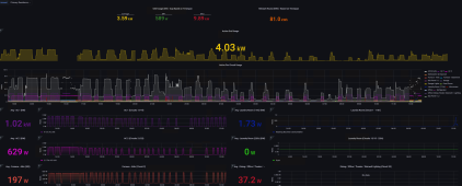
They have an option with just the Large CTs for monitoring power at the main L1 / L2 as well. You can just use their app, or you can use the data to build your own monitoring dashboard. Example:

1659717526512.png
 
Back
Top