diy solar

diy solar

Signature Solar EG4 6.5K Off-Grid Inverter | 6500EX-48

Ok so if you sub out the main breaker in this diagram for a new sub panel that has the grid sent to the inverters that woudl do what i need.

Just a small panel ahead of the inverters is all you need. And it would be N-G bonded if there isn't N-G bond ahead of it. Remove N-G bond in the original main panel.
If i also include the 3 pole double throw, then the grid would take over in the event i overloaded the inverters, batteries, or the passthrough limits of the inverters which appears to be 60A each. I don't know what my highest amperage draw has even been at my house, but i live in the south and it is conceivable that the downstairs inverter mini-split AC, the upstairs AC, the dryer and the water heater could all decide to be running at the same time, and i want the transition from Solar -> Batteries -> Grid to be seamless. Have no desire to sell my expensive power back to the grid :)
As far as seamless, nothing will be seamless when switching from grid to a backup or alternative source or back to grid. Always a delay although the all in one units have a pretty good transfer switch built in, it will still have a delay. Part of the reason is phasing. The 3 pole would allow bypass of the whole inverter/solar system. Fairly seamless, usually just a manual throw switch. Your clocks however would need to be reset unless they are battery powered.

You need to buy a power monitor, I purchased an Eyedro, works well. https://eyedro.com/

It requires a web connection, I guess if they want to spy on my energy usage, they are more than welcome. :ROFLMAO:

Monitor usage for a few months during heavy usage seasons, that would give you an idea of demand.
 
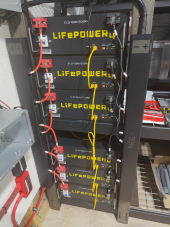
I have this LifePOWER4 version of the EG4 batteries communicating with Solar Assistant, I connected multiple batteries just like your picture shows. I would guess your dip switch setting is not correct, remember after changing the dip switch, you need to power cycle the battery for the new dip switch setting to take effect.

Solar Assistant has the following note: on their EG4 Page.
"Some users reported the dip switches in their EG4 battery manual are the wrong way around. If you are having trouble reading your battery, consider ON might be OFF and/or the first dip switch might be the last."

OK, had some more time to look at it this weekend. Here's what I learned:

Communication with 6500 EX Inverter:

- I had to not only use USB direct, but I also had to plug a USB Cable into BOTH inverters to get full functionality.
~With just one USB cable plugged into one Inverter and parallel cables between the two, I could see some info from both inverters in Solar Assistant (SA), but not all - as soon as I plugged one into each inverter and then into the SA Pi, then all was good.

Communication with EG4 LifePower4 Batteries (No LCD):

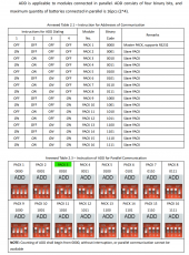
-As instructed by the EG4 Battery section on the SA site, I chose USB to Narada RS485 - when I plugged into the batteries with dip switch 2 in the up position, I could communicate with all batteries independently, but setting the others to 3, 4, etc, I could not. The issue was that It wasn't a Binary 3, 4, 5 etc. After researching the Narada implementation of the RS485 standard, I saw that I needed to set the batteries as follows:

1659823798087.png

The connection from the SA Pi started with the dip switch configured above for 'Pack 3', that shows as my Pack 1. From there, I just configured all of my other batteries as outlined in the picture above, going in order from left to right. I only have 6 batteries at the moment, so I stopped at Pack 8.

Hope this helps someone else.

The only outstanding issue is that though it works for a while, eventually I go back in, and it'll say "No Response. Retrying..." It was doing that before I got all packs added as well. As soon as I disconnect and then reconnect all is well, at least for a while.
 
Ok so if you sub out the main breaker in this diagram for a new sub panel that has the grid sent to the inverters that woudl do what i need. If i also include the 3 pole double throw, then the grid would take over in the event i overloaded the inverters, batteries, or the passthrough limits of the inverters which appears to be 60A each. I don't know what my highest amperage draw has even been at my house, but i live in the south and it is conceivable that the downstairs inverter mini-split AC, the upstairs AC, the dryer and the water heater could all decide to be running at the same time, and i want the transition from Solar -> Batteries -> Grid to be seamless. Have no desire to sell my expensive power back to the grid :)
I used a 3 pole switch and have only needed it once. I did it if the inverters have a problem. I can bypass them and run as normal. I have all my large loads on timers. 240v Hot water is wired as 120v and uses 1200w instead of 5000w. 120 v 3/4 hp Pool comes on after that shuts off after 12pm if I need my dryer it's ok, batteries are full and I just bump my main ac up for an hour. I have a evap cooler, 8k window unit and 3.5 ton a/c (with soft start and on a schedule) on this too and rarely go over 54% load per inverter. I used an Emporia before figuring out what I needed to do. I also used a clamp amp meter on everything prior.
 
OK, had some more time to look at it this weekend. Here's what I learned:

Communication with 6500 EX Inverter:

- I had to not only use USB direct, but I also had to plug a USB Cable into BOTH inverters to get full functionality.
~With just one USB cable plugged into one Inverter and parallel cables between the two, I could see some info from both inverters in Solar Assistant (SA), but not all - as soon as I plugged one into each inverter and then into the SA Pi, then all was good.

Communication with EG4 LifePower4 Batteries (No LCD):

-As instructed by the EG4 Battery section on the SA site, I chose USB to Narada RS485 - when I plugged into the batteries with dip switch 2 in the up position, I could communicate with all batteries independently, but setting the others to 3, 4, etc, I could not. The issue was that It wasn't a Binary 3, 4, 5 etc. After researching the Narada implementation of the RS485 standard, I saw that I needed to set the batteries as follows:

View attachment 105651

The connection from the SA Pi started with the dip switch configured above for 'Pack 3', that shows as my Pack 1. From there, I just configured all of my other batteries as outlined in the picture above, going in order from left to right. I only have 6 batteries at the moment, so I stopped at Pack 8.

Hope this helps someone else.

The only outstanding issue is that though it works for a while, eventually I go back in, and it'll say "No Response. Retrying..." It was doing that before I got all packs added as well. As soon as I disconnect and then reconnect all is well, at least for a while.
Did you connect individually or daisy chained together?
 
You'd need to get some sort of monitoring equipment, like the Emporia Energy Vue - https://www.amazon.com/Emporia-Monitor-Circuit-Electricity-Metering/dp/B08CJGPHL9

They have an option with just the Large CTs for monitoring power at the main L1 / L2 as well. You can just use their app, or you can use the data to build your own monitoring dashboard. Example:

View attachment 105526
@EJansen I use the emporia at my cabin to understand my loads, awesome device. Are you manually importing a CSV or hitting an API directly to graph that data?
 
@EJansen I use the emporia at my cabin to understand my loads, awesome device. Are you manually importing a CSV or hitting an API directly to graph that data?

I deployed the containers from the VueGraf github project and then made my own dashboard layout.


It works quite well.
 
Good day, I see a new manual for the EG4 was released, however in this manual it states :

" Commissioning - Battery Based Note: Systems must be commissioned while connected to battery banks. PV or AC input only based commissioning is not recommended or supported.+

The previous manual did not have a "commissioning" section. However it still states further down on page 38.

" If either “SUB” (solar first) or “SBU” is selected as output source priority and battery is not connected, solar energy and the utility will power the load/s. " which is implying you can still go without a battery and solar + grid.

Will doing this void the warranty now even though theres a section that covers how to perform it?

I dont even know how to ping the guy from signature solar that's on here. Hopefully he sees it.

Reason is some persons may want to supplement their grid use with solar energy until we can consistently eliminate it by affording a battery. But not have to go through the trouble of a grid tied.
 
Honestly, it's probably cheap compared to the whole combiner box, but I agree. Anything to do with RSD is pricey IMO.

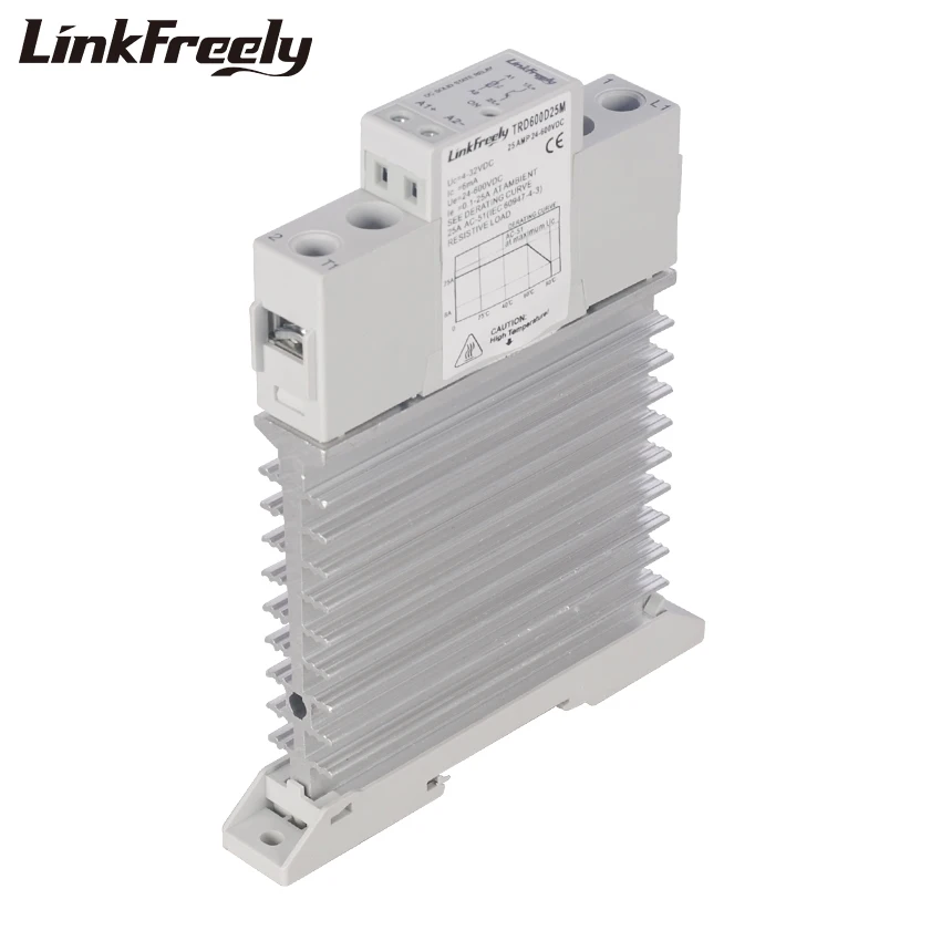
For those interested in RSD for their EG4 6500 Inverters or similar, there appears to be very limited options for string level disconnects these days because of the code changes requiring module level shutdown. The options that are left are somewhat pricey and are limited in nature. In order to stop the inverter from back feeding it looks like coming up with a custom solution appears to be the best option. For those interested, this appears to be somewhat of a cost-effective solution, minus the high shipping costs ($100 for 10 of them - cheapest to just do multiple orders of 4):

TRD600D25M Single Phase DC Solid State Relay SSR 25A DC Control DC Input 4-32V DC Output 24-600VDC Integrated Heat Sink Relay​


You'd need one for the + and - on each string, so with my two strings, that i'll be upping to four in the near future, I'll need to get 8 of these, plus a couple of spares. I'll have them controlled using the same 24v power supply that controls my Tigos, When power is shut off, so too will be the panels, and the back feeding of power from the inverters.

Does anyone see any sort of issue with a setup like this?
 
Good day, I see a new manual for the EG4 was released, however in this manual it states :

" Commissioning - Battery Based Note: Systems must be commissioned while connected to battery banks. PV or AC input only based commissioning is not recommended or supported.+

The previous manual did not have a "commissioning" section. However it still states further down on page 38.

" If either “SUB” (solar first) or “SBU” is selected as output source priority and battery is not connected, solar energy and the utility will power the load/s. " which is implying you can still go without a battery and solar + grid.

Will doing this void the warranty now even though theres a section that covers how to perform it?

I dont even know how to ping the guy from signature solar that's on here. Hopefully he sees it.

Reason is some persons may want to supplement their grid use with solar energy until we can consistently eliminate it by affording a battery. But not have to go through the trouble of a grid tied.
I don't have the answer for that but if it is two units for 240v, there must be a battery. It's somewhere in the manual. I am running two of these, if it was one I would test for you with my battery off.
 
The only problem is it's not UL from AliExpress. You can get these from TTI, and they are UL. I used them for years, they work well. You will need a nice flat heatsink made of aluminum and thermal grease to mount them to it. It is a good solution, but not cheap. Here is the link.

Crydom 2425
 

Attachments

  • sensata-pm22-series-panel-mount-ssrs-datasheet.pdf
    384.6 KB · Views: 8
  • ssc-series-dc-panel-mount-ssr-datasheet.pdf
    825.8 KB · Views: 3
The only problem is it's not UL from AliExpress. You can get these from TTI, and they are UL. I used them for years, they work well. You will need a nice flat heatsink made of aluminum and thermal grease to mount them to it. It is a good solution, but not cheap. Here is the link.

Crydom 2425


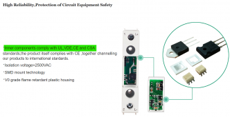
HAHA, but it says this in the description :)

1660089753338.png


Yeah, I was chatting with some folks at Crydom / Sensata yesterday asking for options and they were supposed to get back to me, but they haven't yet. I saw one of the SSC options (SSC1000-25-24) that would have worked but didn't find anything from the PM22 series (which was my preference) - but i'll take another look.

Would definitely rather get something that's more readily available, UL listed, and proven in the field.
 
I am running a 140 ft deep well pump with mine. It pulls around 3200 watts. The two 6500’s handle it fine along with my hvac system
@letech,
What is your surge or is the 3200 it? My surge is about 9000w to start my 240v 3/4hp deep well pump then settles into 1500w.
 
HAHA, but it says this in the description :)

View attachment 106193


Yeah, I was chatting with some folks at Crydom / Sensata yesterday asking for options and they were supposed to get back to me, but they haven't yet. I saw one of the SSC options (SSC1000-25-24) that would have worked but didn't find anything from the PM22 series (which was my preference) - but i'll take another look.

Would definitely rather get something that's more readily available, UL listed, and proven in the field.
Doesn't count if it's not on the label. "inner components comply" is not UL tested as a package.
 
I have a 1hp submergable pump. It spikes at 3200 then settles down to 2700
Man, my surge is killing me for my inverter selection at my cabin. I'm assuming a split phase eg4 6500 would have enough power to start it, but probably at the risk of lowering voltage in the rest of the system for a brief period.
 
Man, my surge is killing me for my inverter selection at my cabin. I'm assuming a split phase eg4 6500 would have enough power to start it, but probably at the risk of lowering voltage in the rest of the system for a brief period.
9000 is steep,what are you checking it with as I want to check my 1hp that is 550 ft down.
 
Man, my surge is killing me for my inverter selection at my cabin. I'm assuming a split phase eg4 6500 would have enough power to start it, but probably at the risk of lowering voltage in the rest of the system for a brief period
 
What is your system wattage capability? You would probably need at least 13kw of inverter power to accomplish that
 
Back
Top