diy solar

diy solar

Signature Solar's new EG4 6000 120/240V inverter

I'm very excited to see more about this unit. It was something I think a lot of people trying to start big loads and having issues on the 6500 will be able to add to their system pretty easily and just have an all around good experience. Good job Signature Solar and EG4!
 
Since I do not have a unit I do not know. Maybe @Marqese can tell us.
If you are referring to an external location on the inverter anywhere to tie an external ground to, such as would originate from a grounding rod, I don't see one on mine.

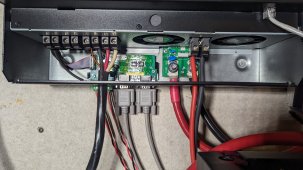
Assuming that EG4 does not want users into the upper portion of the unit, and placed the manufacturing date code sticker over the right hand screw, I have attached a high res picture of the area behind the display.
 

Attachments

  • PXL_20220926_172324942.jpg
    PXL_20220926_172324942.jpg
    434.5 KB · Views: 50
<Warning: RANT MODE ON>
Why can't these $%$#!@& manufacturers give us information on the grounding of the inverter!!! Why do we have to reverse engineer their product to get this basic information? This information is fundimental to understanding how the inverter should be safely wired and yet EG4, MPP and Growatt all leave this critical information out of their manuals. It is nearly criminal negligence!!

Ok... I feel better now.
<RANT MODE OFF>
They want peoples money without assuming any liability for what might happen. At least Watts247 tells potential MPP customers the limitations and uses for his MPP line of Inverters. I have heard him say off Grid Only only on numerous occasions. His competitor is interested in sales so they make it seem safe to use it in any manor possible, even though they know there is really no safe way to wire it. If there was a safe way they would have published it a long time ago.
 
I have one of those MPP inverter from Watts247, Ian was warning about the non-US/European 240vac inverter; because one leg of the 240vac is Neutral, and thus grounded. Fortunately, there's a removable screw on the board as well, which once removed, makes the 240vac out ungrounded/float.

When the inverter is in bypass mode, the AC-input L1/L2/N are directly connected to the internal transformer secondary coil. Is there a concern that this transformer will attempt to balance any imbalance load between L1-N and L2-N ? may be not issue as it would the case with every transformer 240vac device plugging in the house grid.
 
When the inverter is in bypass mode, the AC-input L1/L2/N are directly connected to the internal transformer secondary coil. Is there a concern that this transformer will attempt to balance any imbalance load between L1-N and L2-N ? may be not issue as it would the case with every transformer 240vac device plugging in the house grid.
Yes, It will try to balance both halves..... but depending on what safeties are on the unit it may or may not be a concern.
Suppose the inverter has proper current sensing and perhaps temperature sensing on the transformer's output. In that case, it can detect any significant imballance and disconnect before any damage is done by overheating the transformer.

Every situation is different, but most people report that they see 6-8A of imbalance at most. (Keep in mind that the huge utility transformer is going to be much lower impedance and parallel to the output transformer. It will typically do a pretty good job of keeping the two sides balanced.
 
They want peoples money without assuming any liability for what might happen. At least Watts247 tells potential MPP customers the limitations and uses for his MPP line of Inverters. I have heard him say off Grid Only only on numerous occasions. His competitor is interested in sales so they make it seem safe to use it in any manor possible, even though they know there is really no safe way to wire it. If there was a safe way they would have published it a long time ago.
I see what you are saying, but it seems to me that if they provide better documentation it becomes more the responsibility of the user to ensure it is done correctly. As it is, if a user has a problem they can point to the fact that the manufacturer did not provide proper documentation, thus pushing the blame back on the manufacturer.

I am no Lawyer, but I suspect that since the manufacturer is in China, there are enough hurdles to a successful lawsuit that the distributor may be in more jeopardy than the manufacturer. (Lawyers will always go to where they think they can get money and if they can't get it from the manufacturer, they will look for someone else they can put on the hook)
 
I am no Lawyer, but I suspect that since the manufacturer is in China, there are enough hurdles to a successful lawsuit that the distributor may be in more jeopardy than the manufacturer. (Lawyers will always go to where they think they can get money and if they can't get it from the manufacturer, they will look for someone else they can put on the hook)
True, it's really buyer beware when it comes to cheap products; but I think SignatureSolar really should document these details and alert the US consumers.
 
If going with EG4 units, the 6500EX can be configured to do three phase output. But obviously, to do this natively would take three units, and have their associated idle draw the other 19-20 hours of the day. The EG4 6000EX can't do any kind of single phase output, so doing just one phase of a three-phase setup is out of the question with that model.

I would go with the three units, because pushing 4HP of reasonably heavy motor load for 4-5 hours straight is going to take quite lot of solar and battery to back that up. And during days of heavy clouds, it will take all of three units worth of solar charging to keep a bank of batteries alive, assuming no other load. Those two loads are probably into the 4,000+ watt range while at steady state as these motors are moving water.

On the low end, five hours is 20kWh of usage per day. if you need to consistently do this around the year, I would be over-paneling. But I don't know if you can skip some days, or if there's less usage in the winter or whatever.

Page 56 of the manual describes the setup process for the EG4 6500EX units:

If you were to use a VFD, then you might be able to sneak by with a single EG4 6500EX, as it's transformer based, and should be able to carry those loads if buffered by a VFD that has soft start programmed into the motor startup curve. A single one of my EG4 6000EX won't even come close to starting a 3HP piston compressor (even though it's got a pressure relief on shutdown). Two 6500EX units will start the compressor easily, but have a real hard time with a 5HP cyclone dust collector.

Many folks way smarter than me here that can probably put this more eloquently. I only have my limited testing to go off of.
we need a good 3 phase review on those
 
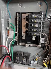
Hey folks! I’m sure I’m over thinking this but want to make sure I get this right. For connecting 2 EG4 6000k to my panel I have 2 40A double pole breakers. The red wires are line 1 from each inverter and the black wires are line 2 from each inverter.

My question is do the 2 reds go on a breaker and the 2 blacks go on another? Or does each breaker get a red and a black? Hopefully this makes sense
A77C4AC8-ECD8-4A0D-9B0F-159233949801.jpeg
 
I have a very similar question and a suggestion or request for videos, if possible:

SUGGESTION: Create Four new videos:


1st Video: on how to wire the AC side from 4 or more 6500EX inverters, into an AC combiner breaker panel, then from that panel out to a critical loads breaker panel, so that the correct wires from each inverter are on the correct leg in the combiner AC breaker panel, and on the correct phase, and discuss if there needs to be any protection to prevent back-feeding from the AC combiner breaker panel back to the other inverters. Please also discuss the safest and preferred location for ground, and ground neutral bond, for the entire system.


2nd Video: on how to wire the AC side from 4 or more 6000EX split phase inverters, into an AC combiner breaker panel, then from that panel out to a critical loads breaker panel, so that the correct wires from each inverter are on the correct leg in the combiner AC breaker panel, and on the correct phase, and discuss if there needs to be any protection to prevent back-feeding from the AC combiner breaker panel back to the other inverters. Please also discuss the safest and preferred location for ground, and ground neutral bond, for the entire system.


3rd Video: What are the maximum quantity of EG4 rack batteries that can be connected to the max number of paralleled 6500s and max number of paralleled 6000s?


4th Video: Can we design a system that exceeds the max number of EG4 rack batteries, by using the max on say 1/2 of the total paralleled inverters, then use another max set of rack batteries on the other 1/2 of the paralleled inverters? If yes how would you wire this set up? Can this be extended to for example if there are a total of 8 paralleled inverters, that we could connect a max quantity of rack batteries to First TWO of the inverters, then another max quantity if rack batteries to the Third and Forth, and so on until you have 4 max sized battery racks each feeding 2 paralleled inverters, in an 8 inverter paralleled system? Please advise.


Thanks
 
Hey folks! I’m sure I’m over thinking this but want to make sure I get this right. For connecting 2 EG4 6000k to my panel I have 2 40A double pole breakers. The red wires are line 1 from each inverter and the black wires are line 2 from each inverter.

My question is do the 2 reds go on a breaker and the 2 blacks go on another? Or does each breaker get a red and a black? Hopefully this makes sense
View attachment 119799
I'm no electrician but I can answer this... I did wire up a growatt before 120/240v.

each Inverter goes to a single double pole breaker.(1 red, 1 black)

Next thing, since this looks like a main panel and not a sub panel you should have someone give some advice on the neutral bonding. That's a tricky subject.
 
Hey folks! I’m sure I’m over thinking this but want to make sure I get this right. For connecting 2 EG4 6000k to my panel I have 2 40A double pole breakers. The red wires are line 1 from each inverter and the black wires are line 2 from each inverter.

My question is do the 2 reds go on a breaker and the 2 blacks go on another? Or does each breaker get a red and a black? Hopefully this makes sense
Great question, and it's not overthinking at all. wire it wrong, and it's a dead short on a single inverter, or across the two inverters. These inverters will survive this, but it's still not a good thing to do.

Make sure the red, black, white, and green are all in the same orientation on both inverters. Worded another way, red and black can go in either location on the inverter, but they should be in the same relative position on both inverters. I would never wire duplicate colors to the same inverter. In other words, never wire both reds to the same inverter or both blacks to the same inverter. Main reason is that you can't readily tell them apart when you need to hook up the breakers on the other end. I mean, you could if you tagged them, but otherwise not.

Then one red and one black to each breaker, but those must be in the same orientation as well. Pick either red or black to be the top wire in the breaker and always hold to that same standard, regardless of how many inverters you have. Also, both wires from any specific inverter need to be connected to the same breaker. Never cross wires between inverters and breakers.

Hope this helps!
 
I'm no electrician but I can answer this... I did wire up a growatt before 120/240v.

each Inverter goes to a single double pole breaker.(1 red, 1 black)

Next thing, since this looks like a main panel and not a sub panel you should have someone give some advice on the neutral bonding. That's a tricky subject.
So as @Marqese asked, is this a main panel that's being converted to have input from the inverters, or are the inverters the only thing that will ever power this panel?
 
I have a very similar question and a suggestion or request for videos, if possible:

SUGGESTION: Create Four new videos:

1st Video: on how to wire the AC side from 4 or more 6500EX inverters, into an AC combiner breaker panel, then from that panel out to a critical loads breaker panel, so that the correct wires from each inverter are on the correct leg in the combiner AC breaker panel, and on the correct phase, and discuss if there needs to be any protection to prevent back-feeding from the AC combiner breaker panel back to the other inverters. Please also discuss the safest and preferred location for ground, and ground neutral bond, for the entire system.

2nd Video: on how to wire the AC side from 4 or more 6000EX split phase inverters, into an AC combiner breaker panel, then from that panel out to a critical loads breaker panel, so that the correct wires from each inverter are on the correct leg in the combiner AC breaker panel, and on the correct phase, and discuss if there needs to be any protection to prevent back-feeding from the AC combiner breaker panel back to the other inverters. Please also discuss the safest and preferred location for ground, and ground neutral bond, for the entire system.

3rd Video: What are the maximum quantity of EG4 rack batteries that can be connected to the max number of paralleled 6500s and max number of paralleled 6000s?

4th Video: Can we design a system that exceeds the max number of EG4 rack batteries, by using the max on say 1/2 of the total paralleled inverters, then use another max set of rack batteries on the other 1/2 of the paralleled inverters? If yes how would you wire this set up? Can this be extended to for example if there are a total of 8 paralleled inverters, that we could connect a max quantity of rack batteries to First TWO of the inverters, then another max quantity if rack batteries to the Third and Forth, and so on until you have 4 max sized battery racks each feeding 2 paralleled inverters, in an 8 inverter paralleled system? Please advise.
I like the video idea, but no time, so I will try to answer here. It got long fast, but would take hours to mock up, record, edit and post these videos.

1. wire everything in parallel, regardless of number of inverters. only variable is how big the downstream electrical panel needs to be. no feedback protection needed, and in my experience the inverters need to see each other's AC output. I've had errors thrown before with two inverters output enabled, but only one output breaker turned on. the manual has some indications of this as well in the error details. I am not going to definitively state anything the grounding question, as there are way smarter people than me here that can quote the National Electrical Code (NEC) and argue to the death about it. My general rule of thumb is that the power source is also the source of the ground, whether that's grid, generator or inverter. and everything downstream of the power source has separated grounds and neutrals. I originally said for safety, but was corrected here on the forum in favor of this logic preventing ground loops.

2. same thing as #1, other than there being some bigger breaker, or even a main breaker between the combiner panel and the critical loads panel. In Square D Homeline, that can be up to a 125amp breaker IIRC. but you could also back feed out a 125A or 200amp panel that has a large bolt in main breaker. I am not sure that main breakers are of the same fast acting design as individual breakers are though. Again, I defer to the NEC code guys here.

3. This would depend upon if you wanted the inverters to manage the batteries or not. Otherwise, if everything is in parallel, there's no limit as to how many batteries that you could hook up in parallel, assuming you could get large enough bus bars to terminate everything.

4. You could split the system like that, and I think that things would stay close to balance, but they could drift further out of balance over time just due to random variations in all of the battery states through a given period of usage (whether charging or discharging). But you could just also run everything in parallel on big bus bars. for example, you could buy really heavy duty 8-position bus bars (Victron up to 600amps or Blue Sea up to 1000amps), then stack one inverter and one battery bank on each terminal. most of each inverter's energy would flow to/from the battery bank that's sitting on the same stud, but could easily draw from others on the same bus bar as needed. that's easily eight inverters, so 48kW of inverter power and 48 rack batteries totaling 240kWh of batteries.

Scaled down a bit from that. I have four EG4 6000EX inverters and two racks of batteries. Each rack of batteries I have connected with two wires each for positive and negative. So I double stacked the inverters on the ends of a 4-terminal bus bar, and then put the four power cables from the two racks stacked on the two center bus terminals. for a little extra CDO, I placed one of the power cables from rack 1 on the top of the terminal and the other on the bottom. Same thing for all of the grounds on the second bus bar. I am not betting anyone's life on it, but it's pretty much expandable as far as you want to go. Done right though, I'd expect a $100+ average cost in cables and bus bars per inverter or battery rack that you set up.
 
Great question, and it's not overthinking at all. wire it wrong, and it's a dead short on a single inverter, or across the two inverters. These inverters will survive this, but it's still not a good thing to do.

Make sure the red, black, white, and green are all in the same orientation on both inverters. Worded another way, red and black can go in either location on the inverter, but they should be in the same relative position on both inverters. I would never wire duplicate colors to the same inverter. In other words, never wire both reds to the same inverter or both blacks to the same inverter. Main reason is that you can't readily tell them apart when you need to hook up the breakers on the other end. I mean, you could if you tagged them, but otherwise not.

Then one red and one black to each breaker, but those must be in the same orientation as well. Pick either red or black to be the top wire in the breaker and always hold to that same standard, regardless of how many inverters you have. Also, both wires from any specific inverter need to be connected to the same breaker. Never cross wires between inverters and breakers.

Hope this helps!
Thank you! This helps a ton!
 
So as @Marqese asked, is this a main panel that's being converted to have input from the inverters, or are the inverters the only thing that will ever power this panel?
The inverters are the only thing that will power this panel. The panel is grounded to an 8ft grounding rod I staked in the other side of the wall outside. This is completely offgrid! The rod was pretty easy using water to soften the ground as I went. Did 6ft or so by hand then a sledge hammer for the last bit.
 
The inverters are the only thing that will power this panel. The panel is grounded to an 8ft grounding rod I staked in the other side of the wall outside. This is completely offgrid! The rod was pretty easy using water to soften the ground as I went. Did 6ft or so by hand then a sledge hammer for the last bit. I
There's likely to never be a ground loop between your inverters and the panel, but I would connect that ground rod to the input ground of the inverter. That ground is passed through the unit, and based upon my testing, is also tied to the neutral at the inverter. But this config will keep the neutral and ground separate all the way to the inverter.

As I noted though, I can't imagine there being a ground loop between your inverters and panel though, so I may just be overthinking it. I am always a little leery of downstream ground/neutral bonding because I have a steel building and my breaker boxes are mounted (actually welded) to the building frame. As such, there's always a direct ground path from devices to panel and also panel to panel, so I keep the neutral floating through the entire system, as all of the panels are tied together through my building's steel frame.
Are you saying to connect the grounding rod to the a
 
Back
Top