diy solar

diy solar

Single phase to 100amp panel (one side only?) Does this make sense.

BlueMarblePA

Solar Enthusiast
Joined
Sep 11, 2022
Messages
419
Location
PA
20221109_174728.jpg
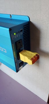
i have this plan to run my 24v 1500 watt inverter to a 100 amp circuit panel. I know that I only have three wires and thus only half the panel will be active and thus only single pole circuit breakers will work, but I am hoping with more and more panels will one day allow me to provide more amps and 240 volts.

Does this make sense?!
 
You actually have 2 options depending on how many loads you wish to connect and how many single pole breakers are needed.
1) Run the neutral wire to the neutral bus, ground wire to the ground bus and the Hot wire from the inverter to 1 pole on the main breaker which will give you power on one of the breaker bus bars.
2) Same as above but use a distribution block to distribute the Hot wire to both poles on the main breaker then you have a full 120V panel. Probably not worth it if you don't need all the breaker spaces initially.
 
Thank you. This confirms my understanding of how electrical panels work. I will just plan to use one side of the panel for now as I have virtually no real loads at this point.

One of the main reasons to buy this electrical panel was so that I could have a proper ground and neutral bond at one place. The shed has no power or connection to the home and thus to the grid. The sine wave inverter has a floating neutral.

I was planning to bring solar panel wires in to the panel ground bus as well? And I was planning to bring the inverter and victron mppt chassis grounds to the same place.
 
One of the main reasons to buy this electrical panel was so that I could have a proper ground and neutral bond at one place. I was planning to bring the inverter and victron mppt chassis grounds to the same place.
Yes, excellent
I was planning to bring solar panel wires in to the panel ground bus as well?
The solar panel frames and racking should have and an equipment ground conductor (EGC) that ties into the ground buss.
On the other hand, neither the + or - current carrying DC wires from the PV panel should be grounded, they run directly to the SCC + and - input, no other connections. The exception to the rule would be if the inverter manual calls for it but that would be unusual.
 
I would be inclined to set it up with the bus between the two hots now and distribute the breakers across the two legs. Reason being that, when you set up 240V you already have your breakers distributed across both legs without making a mess of the panel cover knockouts and a bunch of relabeling. Any 120/240V inverter setup will be happier if the two legs are fairly close to balanced.

I have a panel installed with plan to add 240V where I only attached one hot, and because of the future plans, it has been sitting open. It's in a relatively not too dangerous place for it, but I'd still rate it much safer all around to just arrange breakers in the slots you plan to want them eventually right now and label them properly.
 
Use 2 + ground Romex for your wiring of 120V circuits, not 3 + ground.
Often, L1 goes to black, L2 goes to red, N goes to white. The neutral carries difference between L1 and L2 current.
But with 120V fed to both, neutral would carry L1 + L2 and burn up.

So wire your place like it was an RV, compatible with either 120V on both legs, or 120/240V split-phase.

Consider having 2 panels, one critical loads and one other loads. Or splitting them between the two phases.
If you have an SoC signal available, you can use a load-shed relay to disconnect non-critical loads when battery gets low.
 
Hedges, true, if you missize the wire. Sounds like in this case it's a way oversize breaker panel for the inverter, so a neutral sized appropriately for a future full-size inverter should be fine — for that matter, 14/2 should handle the output of his current inverter. Run 8/3 from inverter, sized for an 8kW inverter and tie black/red together at the inverter for lower line loss. No chance of anything less than a 4kW inverter burning up that neutral. I don't know of a bigger 120V only inverter anyway.

Splitting critical loads on one leg is a decent idea, too.
 
Wow. These are some great ideas. I will see if I can put both hot wires into the same plug that I bought on Amazon. I doubt I will be able to fit 8/3 cord?

ELEGRP Lighted 15 Amp 125 Volt... https://www.amazon.com/dp/B0967JMS79?ref=ppx_pop_mob_ap_share

Then I can run the wire from inverter to the hot terminals of the 100amp electric box and then load both sides of the panel. At present though I doubt I will have more than two circuits. When summer comes I do want to run the pool vacuum - either pump or new electric vacuum

Your main breaker wire clamps can easily accommodate 2 wires since there is absolutely no way you're running any cable larger than maybe #10 from that inverter.

Just put a jumper wire between the two breaker inputs. Will take you 5 seconds and can be easily removed when you get a larger inverter in the future and need to run new/bigger wire.
 
OK. Am partly there. 10/3 soow cable plugged in to the inverter and feeding the panel. I still need to wire a jumper. I did end up using 10 awg crimps because the stranded cable seemed to get smushed by the screws. 20221124_095341.jpg
 
Did you also install a ground rod? If not, then all the exposed metal could float to a dangerous voltage potential.
 
I see it has the green screw to ground enclosure to neutral busbar.
I think the neutral bar is meant to also be ground bar in this configuration.
Was your ground bar sold separately?
When I install an additional ground bar, I like to use copper wire connecting it to the primary ground bar (the bonded neutral in your case).
That way, if a branch circuit has fault to ground, current finds its way back to neutral without having to go through a screw and steel sheet metal. Lower resistance path so chassis of anything on branch circuit is held to a lower voltage.
Then the screw only serves to bond the box itself, in case of a fault to it.
 
Don't bond the neutral and ground in the panel yet until you know if your inverter is gfci.

Making progress!
 
Don't bond the neutral and ground in the panel yet until you know if your inverter is gfci.

Making progress!
My three prong tester says the inverter has an open ground. It is weird because it is only the middle yellow which is open ground. I don't know why it blinks
 

Attachments

  • 20221124_144744.jpg
    20221124_144744.jpg
    75.7 KB · Views: 6
Did you also install a ground rod? If not, then all the exposed metal could float to a dangerous voltage potential.
I installed two eight foot ground bars which are connected by 6awg bare copper to each other and then up to the ground bus bar in the panel
 
Your main breaker wire clamps can easily accommodate 2 wires since there is absolutely no way you're running any cable larger than maybe #10 from that inverter.

Just put a jumper wire between the two breaker inputs. Will take you 5 seconds and can be easily removed when you get a larger inverter in the future and need to run new/bigger wire.
I put a 10awg jumper but then I removed it because I am having problems
 
I need everybody's help. I connected a standard circuit breaker with 12/2 romex and wired it to a gfci outlet, but the leviton blinks red and I can't get it to reset. I pressed test and reset and it won't trip.

I then removed the standard breaker and wired in the afci/gfci breaker (expensive) and it has one yellow light blinking. It won't turn on.

I think it might have something to do with the inverter input ac? Maybe if it is not grounded coming in, even if I have a ground in the panel, it detects a problem?

Make a quick pigtail with a plug on one end and wire the other end to the gfci outlet and then plug it directly into the inverter and see if it will operate as normal.

Also, check to make sure hot and neutral aren't reversed.
 
Back
Top