Howdy from Texas! It hot so what better time to start a solar power project and work outside!
Jokes aside, I've got a question regarding this initial startup project I have going. This is my first foray into solar and I believe I have a good start to this milk crate/small power box unit it seems I am putting together. I've been running all sorts of numbers (even before finding FilterGuy's energy audit spreadsheet here...cheers for that!) and think I've got it laid out. I'll post a scribbled on modified copy of Will's schematic here so I can show what I am looking at.

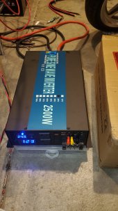
The inverter I've selected is the following: Krieger 1100 W Pure Sine
This unit is advertised to work down to 10.5 V, comes with its own cables (think I saw 2 AWG but cannot confirm with the 1100 W unit) and a fuse (again, I saw in a Q&A that its a 110 A). My conundrum is the interaction between the inverter and battery and sizing the wires and main fuse. I've seen a number of threads here with good information but they seem to disagree in the size requirements. For the most part, bigger is better, but it causes problems for weight and finances. I've been back and forth multiple times through charts and explanations and at this point my head is spinning. I'm really just wanting to know if I have the wires and fuse sized correctly. Been back and forth between 2 and 2/0 AWG and 125, 150, 175 and 200 A for these items so now I'm just confusing myself with differing requirements...and the BMS doesn't help clarify that issue with the 150 A overcurrent protection.
This system was originally sized a bit larger (1500 W inverter with corresponding increases in wires/fuse) but given its use case, the battery (12 V, 100 Ah) and BMS became the limiting factor, so I needed to scale it down some. I intend on buying cells and a BMS and assembling my own battery too, and that's another issue but one that I think is more straightforward and fairly well documented.
This has shaped up to be a cool but really nerve-wracking project. Just want to make sure my first shot scores a hit!
Jokes aside, I've got a question regarding this initial startup project I have going. This is my first foray into solar and I believe I have a good start to this milk crate/small power box unit it seems I am putting together. I've been running all sorts of numbers (even before finding FilterGuy's energy audit spreadsheet here...cheers for that!) and think I've got it laid out. I'll post a scribbled on modified copy of Will's schematic here so I can show what I am looking at.
The inverter I've selected is the following: Krieger 1100 W Pure Sine
This unit is advertised to work down to 10.5 V, comes with its own cables (think I saw 2 AWG but cannot confirm with the 1100 W unit) and a fuse (again, I saw in a Q&A that its a 110 A). My conundrum is the interaction between the inverter and battery and sizing the wires and main fuse. I've seen a number of threads here with good information but they seem to disagree in the size requirements. For the most part, bigger is better, but it causes problems for weight and finances. I've been back and forth multiple times through charts and explanations and at this point my head is spinning. I'm really just wanting to know if I have the wires and fuse sized correctly. Been back and forth between 2 and 2/0 AWG and 125, 150, 175 and 200 A for these items so now I'm just confusing myself with differing requirements...and the BMS doesn't help clarify that issue with the 150 A overcurrent protection.
This system was originally sized a bit larger (1500 W inverter with corresponding increases in wires/fuse) but given its use case, the battery (12 V, 100 Ah) and BMS became the limiting factor, so I needed to scale it down some. I intend on buying cells and a BMS and assembling my own battery too, and that's another issue but one that I think is more straightforward and fairly well documented.
This has shaped up to be a cool but really nerve-wracking project. Just want to make sure my first shot scores a hit!