diy solar

diy solar

Sizing Inverter to Inrush Current?

OK - so, based on the inrush and MPP not really up for taking a hard momentary surge amperage draw, MPP recommended I go with TWO of their LV6548 running in parellel to give me my 240 split voltage. Each of the units is rated for 6,500 watts continuous.

My MAX inrush current (if everything magically started at once) would be about 45 amps on each unit. My question of the moment is how much battery do I need to connect to each unit. I will be using 48 volt batteries. The audit and sizing excel sheet on this site showed I needed 25,888 watt hrs to run two days with no charge. That seems really high considering how low the running amperage and duty cycles are, but assuming it is accurate, that would be almost 550 Amp-hours. Seems high. Thoughts? Aaccording to the excel sheet and all my math, to run fridge, sump pump, well pump and oil fired furnace, I will need:
Two of the LV6548's (for 13kw output) for about $3,0000
Six 48V 100AH 5.12KWH LIFEPO4 batteries for about $10,000
Misc cables to hook that portion up - at least afew hundred $$$

Then, I will need at least 4,000 watts of solar panel to charge it (according to the sizing tool/excel sheet).

The inverters and batteries are way bigger than I expected I needed. Am I doing the math wrong, or am I just an overly optimistic solar newbee?
 
Yes, overly optimistic. To answer your other question, I was starting a 38A load on my XW+6848 on a 377Ah Trojan battery with 4500W of solar. Worked fine for years, though I finally upgraded to a 568Ah Rolls battery
Was 38 amps the starting current or the running current?
 
Was 38 amps the starting current or the running current?
Yes, 38A starting, 9.5A running. Here's one additional factoid. When starting out, I measured 10.1A running and pumped 275GPH when powering the pump with my generator. Once I switched to solar made with my XW, I got 305GPH, while only consuming 9.5A. That's because the AC from the inverter is cleaner than from the generator, and the smoother running pump produces more water for less power.
 
Yes, 38A starting, 9.5A running. Here's one additional factoid. When starting out, I measured 10.1A running and pumped 275GPH when powering the pump with my generator. Once I switched to solar made with my XW, I got 305GPH, while only consuming 9.5A. That's because the AC from the inverter is cleaner than from the generator, and the smoother running pump produces more water for less power.
Wow. That's completely unexpected. I would think it is a dumb pump, and 60hz/close enough is close enough and would run the pump, and a cleaner wave would make almost no difference. Interesting that it was that measurable.

I have gotten a few suggestions to run the pump off a variable freq drive so I can reduce the inrush current. Did you consider that, and if so, why did you rule it out?
 
I have gotten a few suggestions to run the pump off a variable freq drive so I can reduce the inrush current. Did you consider that, and if so, why did you rule it out?
A lot of the folks here are building entry level systems with budget components. If I'm not feeling nice, I'd say toy components for play-solar systems. I have an off-grid homestead that needs completely dependable power. It is not a toy system. If my systems fails and I don't have my generator backup, 120 orchard trees die.

Having had to pull a heavy 240VAC pump 400 feet out of the ground before, I'm not inclined to swap out this pump or that pump on another's suggestion. The simplest, most cost effective solution was to make a system to power what I already have in the ground rather than come up with make-it-work ideas that are not guaranteed to work.
 
The audit and sizing excel sheet on this site showed I needed 25,888 watt hrs to run two days with no charge.
Six 48V 100AH 5.12KWH LIFEPO4 batteries for about $10,000

The inverters and batteries are way bigger than I expected I needed. Am I doing the math wrong, or am I just an overly optimistic solar newbee?

Batteries are the most expensive part.
Can you shut off most loads any time batteries drop to 80% or 50% state of charge? Just do without until the sun returns?
Then a much smaller battery, just enough to start motors and run a light overnight, would be enough.

With PV costing less than battery, you might do a larger PV array so less draw on battery.
My system is grid-backup for power failures (grid tie PV the rest of the time.) Battery is enough for one night, to 70% DoD. PV puts out that many Wh in about 1 hour. It lets me run A/C all day long.
 
A lot of the folks here are building entry level systems with budget components. If I'm not feeling nice, I'd say toy components for play-solar systems. I have an off-grid homestead that needs completely dependable power. It is not a toy system. If my systems fails and I don't have my generator backup, 120 orchard trees die.

Having had to pull a heavy 240VAC pump 400 feet out of the ground before, I'm not inclined to swap out this pump or that pump on another's suggestion. The simplest, most cost effective solution was to make a system to power what I already have in the ground rather than come up with make-it-work ideas that are not guaranteed to work.
I had the same exact mindset - I don't have an orchard, but I dso know the cost and effort to pull up a well pump that is 300 feet down. I was spooked to do anything to change any part of that well pump system. I was getting a lot of advice to "just soft start it or put it on a var freq drive)." Figured maybe I was just worrowing for nothing. Happy to hear I'm not alone.
 
New to solar, and looking at the MPP "all in one" inverters. Trying to figure out how large I need to go, so I measured inrush and running current on the 4 things I plan to run (a well pump, oil furnace, sump pump and fridge). My question is: do I need to size the inverter to accommodate the worst case of all 4 things starting at the same time? (i.e. do I size to inrush or running?)

For info:
Load / Inrush / Running
Fridge - 1.1A - .87A
Furnace - 28.9A - 7A
Sump pump - 16.88A - 9.4A
Well Pump (240 V) L1 - 23.1A - 6.5A
Well Pump (240v) L2 - 22.5A - 6.6A
(yes, I know the two legs on the well pump should probably be the same, so I chalk that up to the meter, or one of the legs being used for control of pump)

Based on this, total inrush amperage (if everything started at once) is 92.48A which is 11,097 watts (I think)
Total running amps is 30.27A (if everything is on at the same time) which would be 3,632 watts

My concern is the house is normally not inhabited. If everything happened to start at the same time, I don't want to overload the inverter and have it shutdown. If I lived there, I could go down and shed some load and start it back up; but since I'm mostly not there, the inverter might just sit there in the fault state and I would have no heat.

Advice/help/corrections to any mistakes or assumptions above are all appreciated.

My followup question is going to ask about opinions about paralleling two inverters vs just buying the units that are really two units paralleled inside (like the MPP LVX6048). So feel free to opine on that as well if you like.


Thanks in advance!
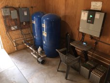
Hi, this is a great question. I ran into some issues, which may be helpful, adding emergency power for our pumphouse. For our water supply, we have a 400' deep well which pumps water with a submerged 3/4 HP motor, delivering ~6.5GPM to a 2500 Gallon tank. We have a 1.5 HP booster pump/pressure tanks which delivers water at ~45PSI to our home. Both well and booster pump motors operate at 240V.

It worked great, but I soon realized that losing power would result in no water, so I decided to add emergency power for up to 24hrs. I assumed that despite my wife's best efforts, the 2500Gallon tank would last a couple of days if we lost power, so I sized the system for just the booster pump.

Phase-I configuration was MPP LV5048 and 14s/4p Nissan leaf NMC cells. I have a 16 panel solar array which provides sufficient power to keep the batteries charged up. The MPP LV5048 uses a high frequency inverter, which in my experience has a poor inrush current capability, but has sufficient capacity (5KW) to start and power the 1.5HP booster pump.

For phase-II I added the wrell pump but the combination of startuip current (booster pump) + operating current (well pump) was just too much for the inverter so I included a relay, with no additionl time delay, to prevent the well pump operating when the booster pump was powered. I really like the features on the LV5048 especially that you can prioritze the power source.

For Phase-III I powered the barn as well, which has a fridge, 10 LED shop lights, a drill press, mitre saw and table saw. I had to add a soft start to the mitre saw and table saw to avoid over powering the LV5048.

I do need to add control of the well pump to operate only during the day, when solar is available, to prevent the batteries from discharging in the evening. So with a little help you can get the LV5048 to power your well pump and more.

Observations:
The LV5048, or the newer LV6048, are awesome pieces of hardware but the limitation is that they are really are 2 x 2.5KW/2x3.0KW inverters connected to look like 5KW/6KW split phase. They will provide 5KW/6KW for a balanced 240V load, but only 2.5KW/3.0KW for a 120V load. If I had to choose again, I would get an all-in-one unit with a low frequency inverter, or a 240V high frequency inverter and use an external auto transformer since they seem to handle the inrush currents much better. My LV5048 is wired to the UTILITY and charges the batteries if they get below 50% SOC.

I'm not exactly sure why, but it seems that the transformer stores sufficient magnetic energy to provide the required inrush current, which is typically 3-4x the operating current of the motors.

I was surprised by how much the operating current was for the motors. My calculations show they are only ~50% efficient. I will replace them with brushless DC motors if they ever fail.

You might want to build a 24hr model for your configuration and measure both operating currents and inrush currents to make sure your inverter and batteries can handle the load.

I'd be glad to try and help if you have any questions.

Good luck, Brian
 
I had the same exact mindset - I don't have an orchard, but I dso know the cost and effort to pull up a well pump that is 300 feet down. I was spooked to do anything to change any part of that well pump system. I was getting a lot of advice to "just soft start it or put it on a var freq drive)." Figured maybe I was just worrowing for nothing. Happy to hear I'm not alone.
I think you made the right call. There are some applications where soft start is OK, such as a mitre or table saw, but as I understand a standard well pump requires a large initial torque to operate correctly resulting in a high inrush current (3-5X operating current), which must be supplied by the utility or the inverter.
 
Hi, this is a great question. I ran into some issues, which may be helpful, adding emergency power for our pumphouse. For our water supply, we have a 400' deep well which pumps water with a submerged 3/4 HP motor, delivering ~6.5GPM to a 2500 Gallon tank. We have a 1.5 HP booster pump/pressure tanks which delivers water at ~45PSI to our home. Both well and booster pump motors operate at 240V.

It worked great, but I soon realized that losing power would result in no water, so I decided to add emergency power for up to 24hrs. I assumed that despite my wife's best efforts, the 2500Gallon tank would last a couple of days if we lost power, so I sized the system for just the booster pump.

Phase-I configuration was MPP LV5048 and 14s/4p Nissan leaf NMC cells. I have a 16 panel solar array which provides sufficient power to keep the batteries charged up. The MPP LV5048 uses a high frequency inverter, which in my experience has a poor inrush current capability, but has sufficient capacity (5KW) to start and power the 1.5HP booster pump.

For phase-II I added the wrell pump but the combination of startuip current (booster pump) + operating current (well pump) was just too much for the inverter so I included a relay, with no additionl time delay, to prevent the well pump operating when the booster pump was powered. I really like the features on the LV5048 especially that you can prioritze the power source.

For Phase-III I powered the barn as well, which has a fridge, 10 LED shop lights, a drill press, mitre saw and table saw. I had to add a soft start to the mitre saw and table saw to avoid over powering the LV5048.

I do need to add control of the well pump to operate only during the day, when solar is available, to prevent the batteries from discharging in the evening. So with a little help you can get the LV5048 to power your well pump and more.

Observations:
The LV5048, or the newer LV6048, are awesome pieces of hardware but the limitation is that they are really are 2 x 2.5KW/2x3.0KW inverters connected to look like 5KW/6KW split phase. They will provide 5KW/6KW for a balanced 240V load, but only 2.5KW/3.0KW for a 120V load. If I had to choose again, I would get an all-in-one unit with a low frequency inverter, or a 240V high frequency inverter and use an external auto transformer since they seem to handle the inrush currents much better. My LV5048 is wired to the UTILITY and charges the batteries if they get below 50% SOC.

I'm not exactly sure why, but it seems that the transformer stores sufficient magnetic energy to provide the required inrush current, which is typically 3-4x the operating current of the motors.

I was surprised by how much the operating current was for the motors. My calculations show they are only ~50% efficient. I will replace them with brushless DC motors if they ever fail.

You might want to build a 24hr model for your configuration and measure both operating currents and inrush currents to make sure your inverter and batteries can handle the load.

I'd be glad to try and help if you have any questions.

Good luck, Brian
Brian - thanks for all the info (and it's a bit comforting to see someone on the same path). I ended up going with the Growatt 12k - it has a transformer and the *spec sheet* says it can handle 3x rated for starting (but, that's a number on paper - like my height listed on my drivers license). I *think* I will be able to handle everything starting at once (in case it ever did).
I like your idea of pumping water to the surface and then booster pumping from there - but I'm in a climate where if that water was stored outside, it would freeze. I'm pondering storing water inside - maybe 250 or 500 gallons. I was spooked about adding relays to only allow some things to run when others are not - I figured it would make troubleshooting a problem more complex (really more worried that if I call in a repair person when I'mnot there, HE will have trouble understanding it).
Same thoughts as you on motor current - my blower fan in my furnace turns out to be a hog. Who knew?
What are you using for the soft start on the miter saw? I wanted to power my barn - mostly lights, but I also have a miter saw and table saw and knew those would blow away the inverter if I tried to run them.
What panels did you use, and where did you mount them, and if roof, did you do it yourself? My inverter should get to me i a few weeks. Batteries are supposed to arrive late December. I figure if I can get panels sooner rather than later, I can mount them on my shingle roof in the spring. My plan is to charge batteries off utility if needed (and off panel once they are up)
 
Induction motors don't usually get terribly hot, so I don't think they are inefficient (like 50%), but rather have a power factor considerably different from 1.0; they draw and return current out of phase.

How an inverter deals with that would be one question - does it capture the returned current back into capacitors?
Maybe a "run" capacitor could be added to the furnace fan to improve its power factor.

Hope that can be accomplished without paying the Grangers price


Brian - thanks for all the info (and it's a bit comforting to see someone on the same path). I ended up going with the Growatt 12k - it has a transformer and the *spec sheet* says it can handle 3x rated for starting (but, that's a number on paper - like my height listed on my drivers license). I *think* I will be able to handle everything starting at once (in case it ever did).
I like your idea of pumping water to the surface and then booster pumping from there - but I'm in a climate where if that water was stored outside, it would freeze. I'm pondering storing water inside - maybe 250 or 500 gallons. I was spooked about adding relays to only allow some things to run when others are not - I figured it would make troubleshooting a problem more complex (really more worried that if I call in a repair person when I'mnot there, HE will have trouble understanding it).
Same thoughts as you on motor current - my blower fan in my furnace turns out to be a hog. Who knew?
What are you using for the soft start on the miter saw? I wanted to power my barn - mostly lights, but I also have a miter saw and table saw and knew those would blow away the inverter if I tried to run them.
What panels did you use, and where did you mount them, and if roof, did you do it yourself? My inverter should get to me i a few weeks. Batteries are supposed to arrive late December. I figure if I can get panels sooner rather than later, I can mount them on my shingle roof in the spring. My plan is to charge batteries off utility if needed (and off panel once they are up)
Thanks for the reply. I think you are definitely on the right track.

Well I can claim no credit for the well/booster pump combination idea, it was like that when we moved in. To answer your questions:
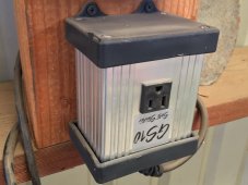
1. Soft Starter: Miter/Table saw soft starter is a GS10 Soft Starter. Not cheap, but really works. I think I bought it on Amazon.
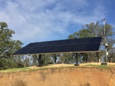
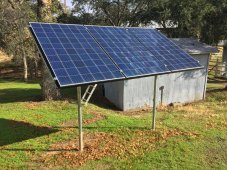
2. Panels: I started with a 3 array of 270W Renogy panels mainly because the shipping was "free". I upgraded to a ground mount of 16 x 310W panels. I bought the UNIRAC ground mount and the panels from RENVU, who are great to work with. I'm pretty old, and did most of the work myself, so it took a long time to complete (months). I connected both small an d larger array to PV2 and PV1 inputs on the LV5048. BTW, the ground mount is connected as 5 strings of 3 panels in series, mainly because of the limited voltage range of the MPPT controller on the LV5048. The combiner box (midnight solar) is on the ground mount side and I'm running 6AWG cable (very expensive) since the pumphouse/powerhouse is 180' away. The extra panel is used to power a remote PTZ camera.

Changes I'd make are using an LF inverter, the Growatt 12K looks a perfect choice to me. I would use LiFePO4 battery chemistry. Of course the devil's in the details and it would take hours of boredom to tell you everything and all the mistakes I made. My advice is just hang in there and safety first !

If there is anything I can help with and share my lack of wisdom, just ask.
Brian
 

Attachments

  • IMG_0312.JPG
    IMG_0312.JPG
    219.9 KB · Views: 8
  • IMG_0314.JPG
    IMG_0314.JPG
    327.6 KB · Views: 8
  • IMG_0315.JPG
    IMG_0315.JPG
    188 KB · Views: 8
  • IMG_0316.JPG
    IMG_0316.JPG
    601.7 KB · Views: 9
Induction motors don't usually get terribly hot, so I don't think they are inefficient (like 50%), but rather have a power factor considerably different from 1.0; they draw and return current out of phase.

How an inverter deals with that would be one question - does it capture the returned current back into capacitors?
Maybe a "run" capacitor could be added to the furnace fan to improve its power factor.

Hope that can be accomplished without paying the Grangers price


You're right, and I should have mentioned about the PF. Measurements from the LV5048 for the 3/4 HP well pump were:
POWER: 788W, 971VA
The PF = 788/971 = 0.81. For 100% efficiency and PF = 1.0, the 3/4 HP* motor should use 0.75*746 = 560W(or VA).
So the efficiency of the motor is 560/971 = 58%, and with PF correction, I could improve this to 71%.

* The well pump is down the well so I'm taking the HP rating at face value from the installer.
This is not the proper calculation. When a pump is rated as having 3/4hp, it means that the force of the water coming out of the pump has the force of 3/4 hp, not the amount of electricity it takes to run it. I had just mentioned this in another post. Assuming your motor is approximately 1/3rd efficient in converting electricity into force, you need 3X the amount of electricity to equal that force. So, the proper calculation is 3/4hp X 746W X 3X = 1679W.

Again, I should mention that real-world measurements always trumps pen and paper calculations. The best thing you can do is measure the current draw on your pump and go from there.
 
Last edited:
This is not the proper calculation. When a pump is rated as having 3/4hp, it means that the force of the water coming out of the pump has the force of 3/4 hp, not the amount of electricity it takes to run it. I had just mentioned this in another post. Assuming your motor is approximately 1/3rd efficient in converting electricity into force, you need 3X the amount of electricity to equal that force. So, the proper calculation is 3/4hp X 746W X 3X = 1679W.

Again, I should mention that real-world measurements always trumps pen and paper calculations. The best thing you can do is measure the current draw on your pump and go from there.
Thanks for the reply. Not sure I entirely agree with you. The rating on a motor as you say, is mechanical. So a 3/4 HP motor can provide that much mechanical power to do whatever you want, in my case pump water from a well, and meet the spec on the nameplate. The amount of mechanical energy needed to pump water, depends on the head and the flow. For low water velocity, it's a simple potential energy problem (E=m*g*h)
The electrical energy required to achieve the rated mechanical power output = mechanical power/(mechanical-electrical efficiency). The losses in the system are both electrical, such as wire resistance losses and eddy currents and mechanical, such as friction in the bearings and the pipe.

Under "normal" operating conditions, full load with with PF correction, the electrical to mechanical efficiency of a motor is very good, in the range of 70-90%, so I think your 1/3 is not accurate. At startup , of course, there is a large inrush current (locked rotor current) which exceeds the normal operating current by 3-5X.
 
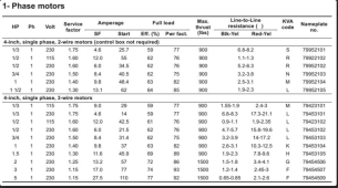
Here is a pump table that was previously provided by another member, Mike94450 I believe. Looking at the published numbers, the required amps/watts drawn by each motor align closely with the 33% efficiency rule. But, as I've admonished people over and over here, real-world measurements trumps pen and paper every time. That's what I've done for my own pump, and that's what I recommend to everyone else.
1636407375981.png
 
Here is a pump table that was previously provided by another member, Mike94450 I believe. Looking at the published numbers, the required amps/watts drawn by each motor align closely with the 33% efficiency rule. But, as I've admonished people over and over here, real-world measurements trumps pen and paper every time. That's what I've done for my own pump, and that's what I recommend to everyone else.
View attachment 71757
Not sure which columns you are using, perhaps for a 3/4 HP motor Pin = 230V x 8.4A = 1932W. But I think this is the maximum current at a SF = 1.5.
For a 3/4 HP motor, the Full Load Eff (%) is specified as 62% and not (3 / 4 * 746) / (230 * 8.4 ) = 29%, as you may have calculated.
 
Not sure which columns you are using, perhaps for a 3/4 HP motor Pin = 230V x 8.4A = 1932W. But I think this is the maximum current at a SF = 1.5.
For a 3/4 HP motor, the Full Load Eff (%) is specified as 62% and not (3 / 4 * 746) / (230 * 8.4 ) = 29%, as you may have calculated.
The two amperage collumns are SF and Start, which correspond to the running and starting amps. I usually look at the value for the 1hp 3-wire pump, which I actually have in the ground right now. In the case of the 1hp 230V 3-wire pump those values are 9.8A and 37A, which track very closely to my actual measurements of 9.5A and 38A. Now my Schneider is running at 235V, so 235V X 9.5A =2233W. 746W (1hp) X 3X = 2238W, an almost perfect match. So, my real-world measurements match what I was trying to state almost exactly. Whether or not I'm using the right terminology to explain the answer may not be as correct, though I think the numbers are.
 
The two amperage collumns are SF and Start, which correspond to the running and starting amps. I usually look at the value for the 1hp 3-wire pump, which I actually have in the ground right now. In the case of the 1hp 230V 3-wire pump those values are 9.8A and 37A, which track very closely to my actual measurements of 9.5A and 38A. Now my Schneider is running at 235V, so 235V X 9.5A =2233W. 746W (1hp) X 3X = 2238W, an almost perfect match. So, my real-world measurements match what I was trying to state almost exactly. Whether or not I'm using the right terminology to explain the answer may not be as correct, though I think the numbers are.
Thanks for your comment. Can't argue with measurements. I'll retake some measurements from my LV5048 tomorrow for the well (3/4 HP) and the booster pump (1 1/2 HP) just for comparison. BTW, both of these pumps are pretty old and both are 240V.
 
Back
Top