ericfx1984
Solar Enthusiast
- Joined
- Oct 10, 2021
- Messages
- 740
So I have been in the process of bringing the voltage up on a 4p4s, 304 amp hour battery
Started out at 3.3 volts when the cells were delivered and I'm really only getting between 13 and 18 amps when the BMS is hooked up
Since I purchased two bms's I thought maybe it was a limitation of the BMS and I figured I could work around that by attaching the second BMS despite the load.. but it's still only charged at about 16 amps
So then I thought for entertainment I would connect directly to the battery, bypassing the BMS for a few minutes and sure enough it shot up to about 28 amps of charge curre
I'm not really sure I understand why it would do this.. it doesn't make a whole lot of sense to me.. anyway I've reattached the BMS and I'm charging through the BMS.. but I still have absolutely no idea what is going on
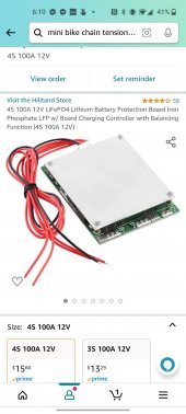
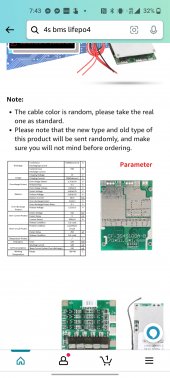
Update:. (also added picture)
This is one of these little cheap jobs maybe 3 in by two and a half inch got it on Amazon for $15 I just needed some type of battery management system for the initial charge to get it close so that I could then reconfigure to parallel and do proper top balance afterward
Started out at 3.3 volts when the cells were delivered and I'm really only getting between 13 and 18 amps when the BMS is hooked up
Since I purchased two bms's I thought maybe it was a limitation of the BMS and I figured I could work around that by attaching the second BMS despite the load.. but it's still only charged at about 16 amps
So then I thought for entertainment I would connect directly to the battery, bypassing the BMS for a few minutes and sure enough it shot up to about 28 amps of charge curre
I'm not really sure I understand why it would do this.. it doesn't make a whole lot of sense to me.. anyway I've reattached the BMS and I'm charging through the BMS.. but I still have absolutely no idea what is going on
Update:. (also added picture)
This is one of these little cheap jobs maybe 3 in by two and a half inch got it on Amazon for $15 I just needed some type of battery management system for the initial charge to get it close so that I could then reconfigure to parallel and do
 proper top balance afterward
Last edited:


