I am off-grid and I have a pair of the SI-6048-US wired in split phase config - working well. (7.5K PV with 2 Midnite 250's and 24kwh Li-Ion battery, REC BMS) I want to attach a 11kw Generac for when the sun doesn't shine. My problem is I am getting a 10V reading on the AC2 Gen/Grid Neutral connection of the Sunny Island Master. I attached the generator wires L1 to Master, L2 to Slave, Neutral split with equal length wires going to both SI's. Is this wiring from the genset correct? When I power up I get an error on slave about the voltage present on the line. It is not tied in to the genset yet. Why is there voltage present on AC2 is my dilemma? Thanks for any input.


You are using an out of date browser. It may not display this or other websites correctly.
You should upgrade or use an alternative browser.
You should upgrade or use an alternative browser.
SMA Sunny Island 6048 Generator install
- Thread starter SoOrSolar
- Start date
svetz
Works in theory! Practice? That's something else
Can you post a diagram out of your manual?
AFAIK, L1 should go to L1, L2 should go to L2, neutral to neutral, I'm not sure what Slave or AC2 are (slave is usually a wire that connects two inverters to keep the phases in sync). What does the manual say about them?
AFAIK, L1 should go to L1, L2 should go to L2, neutral to neutral, I'm not sure what Slave or AC2 are (slave is usually a wire that connects two inverters to keep the phases in sync). What does the manual say about them?
The connections look like this 
AC1 is the left 3 terminals which is a/c output L1. Slave refers to Sunny Island #2 which puts out L2 to load. Neutrals tie together from both units. AC2 is the right 3 terminals in the diagram for grid/generator input. The manual implies L1 from gen. goes to Master, L2 goes to Slave (SI #2) and the neutral splits and goes to both. My issue is there is 10V on N from the master and when you tie it to the slave, it cause an error. There is no diagram I can find in the manual showing generator tie in for 2 Sunny Islands in 240V split phase operation.
AC1 is the left 3 terminals which is a/c output L1. Slave refers to Sunny Island #2 which puts out L2 to load. Neutrals tie together from both units. AC2 is the right 3 terminals in the diagram for grid/generator input. The manual implies L1 from gen. goes to Master, L2 goes to Slave (SI #2) and the neutral splits and goes to both. My issue is there is 10V on N from the master and when you tie it to the slave, it cause an error. There is no diagram I can find in the manual showing generator tie in for 2 Sunny Islands in 240V split phase operation.
Hedges
I See Electromagnetic Fields!
- Joined
- Mar 28, 2020
- Messages
- 20,535
I use Sunny Island with grid connected rather than generator, but connection wouldn't be any different.
If both grid and generator are present, a digital input would tell Sunny Island which one.
"I attached the generator wires L1 to Master, L2 to Slave, Neutral split with equal length wires going to both SI's. Is this wiring from the genset correct? When I power up I get an error on slave about the voltage present on the line. "
"It is not tied in to the genset yet."
Are you saying you do have wires to the AC input of Sunny Island? And, you do not have the wires tied to the generator? Meaning the wires are just dangling?
And Sunny Island worked fine before you connected dangling wires? In that case maybe they're pickup up coupling from something, but I would expect it to be ignored as voltage out of tolerance. Just connect incoming L1, L2, Neutral together so zero volts present.
"My problem is I am getting a 10V reading on the AC2 Gen/Grid Neutral connection of the Sunny Island Master."
Are you reading 10V with a meter? 10V from "Neutral" to what? Neutral on AC input is hardwired to neutral on AC output. You presumably have neutral on AC output of both Sunny Island connected together. You also need to tie neutral to ground somewhere. My system gets that from AC grid, which has ground rod at main AC panel and neutral bonds to ground there.
"My issue is there is 10V on N from the master and when you tie it to the slave, it cause an error."
Didn't you already have neutral from master tied to neutral on slave prior, and system working, prior to trying to add generator?
Referencing page 22 from the manual and depicted in above message showing AC1 and AC2 connections on the Sunny Islands. I have A/C loads connected to AC1 Master and Slave as shown in the manual. All is working well for 1700 hours so far. I want to hook up my genset to the AC2 terminals labeled Gen/Grid. I plan to tie in as follows: Genset L1 to Master L, Genset L2 Slave L, Neutrals bridged and the ground going to a ground rod and the neutral and ground are bonded in the AC load box which runs to same ground rod. Before I tie in the generator, I checked the terminals on AC2 and I read 120V a/c across N & L (gen/grid input) Is this correct and why?I use Sunny Island with grid connected rather than generator, but connection wouldn't be any different.
If both grid and generator are present, a digital input would tell Sunny Island which one.
"I attached the generator wires L1 to Master, L2 to Slave, Neutral split with equal length wires going to both SI's. Is this wiring from the genset correct? When I power up I get an error on slave about the voltage present on the line. "
"It is not tied in to the genset yet."
Are you saying you do have wires to the AC input of Sunny Island? And, you do not have the wires tied to the generator? Meaning the wires are just dangling?
And Sunny Island worked fine before you connected dangling wires? In that case maybe they're pickup up coupling from something, but I would expect it to be ignored as voltage out of tolerance. Just connect incoming L1, L2, Neutral together so zero volts present.
"My problem is I am getting a 10V reading on the AC2 Gen/Grid Neutral connection of the Sunny Island Master."
Are you reading 10V with a meter? 10V from "Neutral" to what? Neutral on AC input is hardwired to neutral on AC output. You presumably have neutral on AC output of both Sunny Island connected together. You also need to tie neutral to ground somewhere. My system gets that from AC grid, which has ground rod at main AC panel and neutral bonds to ground there.
"My issue is there is 10V on N from the master and when you tie it to the slave, it cause an error."
Didn't you already have neutral from master tied to neutral on slave prior, and system working, prior to trying to add generator?
Hedges
I See Electromagnetic Fields!
- Joined
- Mar 28, 2020
- Messages
- 20,535
It is a puzzle, because no voltage should be present on AC2 input until supplied externally (from grid or generator)
It would seem like Master has the relay incorrectly stuck closed. But I'll assume some sort of "installer error" which could be corrected by moving a wire.
With both Sunny Island shut off, measure ohms from AC1 L to AC2 L of both master and slave. Should be open circuit. If not, disconnect wires and try again. Then you'll know if it is Sunny Island or your wiring.
Some people have had these wired together, trying to supply loads upstream.
Since you're seeing voltage where you shouldn't, good to figure that out before connecting the generator!
Earlier you wrote, "My problem is I am getting a 10V reading on the AC2 Gen/Grid Neutral connection of the Sunny Island Master."
A voltage reading requires connecting meter to two different points. One point is "Neutral" of AC2. Where is the other point?
"Master and Slave" meaning one is configured as Master, one as Slave 1, and they have a data cable between them?
Considering that in the following sentences you talk about planning to bridge neutral and ground between AC2 terminals of master and slave, what neutral and ground connections have you had for the 1700 hours so far?
Is a ground rod already installed? Are neutral and ground already bonded in AC load box (which is presumably wired to AC1)?
Connecting generator L1, L2, N, G to them like this sounds correct.
Inside Sunny Island AC1-N is hardwired to AC2-N, AC1-PE is hardwired to AC2-PE.
(I happen to connect just one lug for N and one for PE; I have "Y" connections externally where the wires to Sunny Island, main panel on grid, and protected loads panel are joined together. I did that because conduit was getting too full for more wires.)
Sounds odd. We don't expect electrical connection from AC1 output of Sunny Island to AC2 input until after it has run for 5 minutes, observed power good on AC2, and synchronized its output to the input. So no voltage should be present.
I have AC2 connected to grid, through 63A 2-pole breakers and a fused disconnect. When I open the disconnect, no voltage is present on the wires leading to AC2. I checked that specifically before touching them to install lightning protection.
Earlier you saw 10V on master AC2 N. What was different about that measurement vs. this one?
10V is a floating, coupled value. I sometimes see small voltage on isolated circuits after turning off a breaker. The wires are adjacent in boxes and conduit. It can't drive any current.
Put a light bulb across that 120V reading (AC2 N & L), see if it lights. Measure voltage. Do same with 10V reading.
That will pull a floating voltage to zero, or show that there is a solid connection.
Check both Master and Slave.
Check Master AC1 L to Slave AC1 L. That should be 240V. The Master and Slave can be isolated, can be stacked in series, can be connected in parallel. They can also be running independently as two masters, not synchronized. Many ways of connecting would support 120V loads on both legs of a panel.
How is Sunny Island configured?
I'm expecting "2Phase2 Split-phase system, 2 Sunny Island"
Which of the following?
"PvOnly Stand-alone grid, no utility grid, no generator
Gen Stand-alone grid with generator
Grid Battery-backup grid
GenGrid Battery-backup grid with generator"
Because you use Midnight SCC not Sunny Boy, less likely it would try to backfeed the generator. But Sunny Island can be configured to backfeed (the grid) and you want to make sure it knows this is a generator.
If Sunny Island is actually feeding AC2, that would indicate relay is closed. I don't think that is supposed to happen unless it sees grid present, or is talking to a Multi-Cluster box.
Earlier you wrote,
"I attached the generator wires L1 to Master, L2 to Slave, Neutral split with equal length wires going to both SI's. Is this wiring from the genset correct?"
Are wires connected to AC2 now? Disconnect them, measure voltages directly at AC2 terminals. Measure voltages directly on wires.
If Sunny Island is working correctly, it would seem the voltage you see has to be coming from the wires. I don't know if you have them going through conduit, out of site where they can be mixed up, or anything.
How about a photo and sketch of the hookup?
It would seem like Master has the relay incorrectly stuck closed. But I'll assume some sort of "installer error" which could be corrected by moving a wire.
With both Sunny Island shut off, measure ohms from AC1 L to AC2 L of both master and slave. Should be open circuit. If not, disconnect wires and try again. Then you'll know if it is Sunny Island or your wiring.
Some people have had these wired together, trying to supply loads upstream.
Since you're seeing voltage where you shouldn't, good to figure that out before connecting the generator!
Earlier you wrote, "My problem is I am getting a 10V reading on the AC2 Gen/Grid Neutral connection of the Sunny Island Master."
A voltage reading requires connecting meter to two different points. One point is "Neutral" of AC2. Where is the other point?
Referencing page 22 from the manual and depicted in above message showing AC1 and AC2 connections on the Sunny Islands. I have A/C loads connected to AC1 Master and Slave as shown in the manual. All is working well for 1700 hours so far.
"Master and Slave" meaning one is configured as Master, one as Slave 1, and they have a data cable between them?
Considering that in the following sentences you talk about planning to bridge neutral and ground between AC2 terminals of master and slave, what neutral and ground connections have you had for the 1700 hours so far?
Is a ground rod already installed? Are neutral and ground already bonded in AC load box (which is presumably wired to AC1)?
I want to hook up my genset to the AC2 terminals labeled Gen/Grid. I plan to tie in as follows: Genset L1 to Master L, Genset L2 Slave L, Neutrals bridged and the ground going to a ground rod and the neutral and ground are bonded in the AC load box which runs to same ground rod.
Connecting generator L1, L2, N, G to them like this sounds correct.
Inside Sunny Island AC1-N is hardwired to AC2-N, AC1-PE is hardwired to AC2-PE.
(I happen to connect just one lug for N and one for PE; I have "Y" connections externally where the wires to Sunny Island, main panel on grid, and protected loads panel are joined together. I did that because conduit was getting too full for more wires.)
Before I tie in the generator, I checked the terminals on AC2 and I read 120V a/c across N & L (gen/grid input) Is this correct and why?
Sounds odd. We don't expect electrical connection from AC1 output of Sunny Island to AC2 input until after it has run for 5 minutes, observed power good on AC2, and synchronized its output to the input. So no voltage should be present.
I have AC2 connected to grid, through 63A 2-pole breakers and a fused disconnect. When I open the disconnect, no voltage is present on the wires leading to AC2. I checked that specifically before touching them to install lightning protection.
Earlier you saw 10V on master AC2 N. What was different about that measurement vs. this one?
10V is a floating, coupled value. I sometimes see small voltage on isolated circuits after turning off a breaker. The wires are adjacent in boxes and conduit. It can't drive any current.
Put a light bulb across that 120V reading (AC2 N & L), see if it lights. Measure voltage. Do same with 10V reading.
That will pull a floating voltage to zero, or show that there is a solid connection.
Check both Master and Slave.
Check Master AC1 L to Slave AC1 L. That should be 240V. The Master and Slave can be isolated, can be stacked in series, can be connected in parallel. They can also be running independently as two masters, not synchronized. Many ways of connecting would support 120V loads on both legs of a panel.
How is Sunny Island configured?
I'm expecting "2Phase2 Split-phase system, 2 Sunny Island"
Which of the following?
"PvOnly Stand-alone grid, no utility grid, no generator
Gen Stand-alone grid with generator
Grid Battery-backup grid
GenGrid Battery-backup grid with generator"
Because you use Midnight SCC not Sunny Boy, less likely it would try to backfeed the generator. But Sunny Island can be configured to backfeed (the grid) and you want to make sure it knows this is a generator.
If Sunny Island is actually feeding AC2, that would indicate relay is closed. I don't think that is supposed to happen unless it sees grid present, or is talking to a Multi-Cluster box.
Earlier you wrote,
"I attached the generator wires L1 to Master, L2 to Slave, Neutral split with equal length wires going to both SI's. Is this wiring from the genset correct?"
Are wires connected to AC2 now? Disconnect them, measure voltages directly at AC2 terminals. Measure voltages directly on wires.
If Sunny Island is working correctly, it would seem the voltage you see has to be coming from the wires. I don't know if you have them going through conduit, out of site where they can be mixed up, or anything.
How about a photo and sketch of the hookup?
svetz
Works in theory! Practice? That's something else
Induced voltage? Have a clamp meter you can get a current reading with?
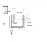
Below is drawing of power wall. The Genset is not wired in at present. I was holding off until I am comfortable with what I am seeing.
I read 120V across N-L at AC2 on both SI-6048. I will measure how much current is present today.
The system is configured 2Phase2 Split-phase system, 2 Sunny Island, PVonly.
No wires attached to AC2 but they will go through a 63A breaker on each leg to the genset. There is no grid at this location.
The earlier comment about the 10V reading was an error, please disregard.
I tend to believe relay is closed also so I do not want to backfeed my generator
Attachments
Hedges
I See Electromagnetic Fields!
- Joined
- Mar 28, 2020
- Messages
- 20,535
Below is drawing of power wall. The Genset is not wired in at present. I was holding off until I am comfortable with what I am seeing.
I read 120V across N-L at AC2 on both SI-6048. I will measure how much current is present today.
The system is configured 2Phase2 Split-phase system, 2 Sunny Island, PVonly.
No wires attached to AC2 but they will go through a 63A breaker on each leg to the genset. There is no grid at this location.
The earlier comment about the 10V reading was an error, please disregard.
I tend to believe relay is closed also so I do not want to backfeed my generator
Do you also have 240V between Master AC2 L and Slave AC2 L? Master AC1 L and Slave AC1 L?
It would be possible to configure either 1Phase2 or 2Phase2, and possible to wire neutral to neutral (correct) or line to neutral (incorrect). Out of the four possible combinations of these, two would produce 120/240 and two would produce 120 (with zero between certain other pairs.
Looking at your drawing, the exact order of (Red, Black, Green) that you showed going to Sunny Island does NOT match the Sunny Island documentation for (L, N, PE) in all cases! Double check that.
Try "Gen Stand-alone grid with generator"
Maybe "PVonly" closes the relays.
The relay needs to be open when grid or generator is first connected.
When Sunny Island is started, it produces output on AC1 first, doesn't connect (to grid in my case) until it has watched voltage on AC2 for a while and then synchronized. Yours appears to have connected AC2 to AC1 by relay without that.
The drawing depicts generally how the wiring connects. The order may not be correct on the drawing but is definitely correct on the units, I do have 240V on AC1 L1 Master and Slave. I will check on AC2. I discovered this by wiring the AC2 connections as pictured but had not tied them into the Genset yet. I powered on the SI's and set the config to 2Phase2 with Grid stand alone with Gen. When I powered up after config, I got an error that there was voltage present on Slave1 AC2. I can't remember error # but did not want to recreate it until I isolated the cause. Unfortunately there is no cell signal at site so I have to do this troubleshooting remotely.
I'm heading to site now and I will check all suggestions. Thanks for the input. BTW, these are units from the DCSolar fiasco with 0 hours when installed.
I'm heading to site now and I will check all suggestions. Thanks for the input. BTW, these are units from the DCSolar fiasco with 0 hours when installed.
Hedges
I See Electromagnetic Fields!
- Joined
- Mar 28, 2020
- Messages
- 20,535
I was going to put my money on "PVonly" causing the issue of power appearing at AC2.
"Gen" ought to be fine, but that caused it to report an error?
"Grid" is what I have, that works.
"GenGrid" should work too.
For either of the __Grid options, you would need to ensure it isn't going to backfeed. For GenGrid that would mean wiring a digital input so it knows generator is what's connected, not grid.
But since you have data link to Midnight charge controllers, I think battery voltage will always be regulated to target value, never higher so shouldn't try to export.
Maybe recreate the original issue using "Gen", see if voltage really is present on Slave1 AC2, also check Master AC2.
Try 1Phase1 and see if everything looks right for a single phase configuration, "Slave" is switched off.
My pallet of Sunny Islands came from the same - their loss is our gain.
Possible errors I see listed:
"W159 1 Voltage on output AC1 slave 1"
"W320 1 Disconnection from utility grid/generator due to excessive external voltage slave 1"
"W336 1 Disconnection from utility grid/generator due to breach of voltage limits of slave 1 (redundant measurement)"
"W340 1 Disconnection from utility grid/generator due to voltage increase protection slave 1"
Thanks for all the input guys. So I went over all of the connections and learned that never assume all is well just because it appears to be working. I did have the N and L reversed on AC1. Fixed that and it allowed the SI's to boot with no stray error in Gen 2Phase2 mode. Being cautious, I began with manual start config of the genset but have not got it to actually charge the batteries while running. That's my challenge to the day since we have 2" snow overnight and 2 more coming tomorrow. Not a lot of PV going on the next 3 days.
the_colorist
"Move over... let me fix it" Installer/Engineer
Does it close the AC2 relay at all? What is your max input amps set to (GnCurNom)?
If you have GnStrMod is set to Manual, check your external meters while the genset is running. Check on both inverters (each showa single phase). Make sure you see the genset input. Ideally your frequency needs to be less than 65HZ. Needs to settle to just under 59.95HZ under full load. If it's outside of the preset operating parameters (manual) then just adjust your genset to accommodate. If you can't adjust the genset, widen the parameters on the SI but be very careful doing this. Only open them up if you know the genset will settle to within operational range under load. For example we have propane sets that sometimes to keep them above 58.95HZ (yes, 58), we need to idle frequency to be 66hz. We know that as soon as it connects, it will begin charging and pull it down (not counting the loads).
If you had a DATA Manager M or a Webbox, those of us that install SMA could quickly check both your settings and current operating values to give you a hand.
Thanks for the input. The homeowner was not available until today to get back to testing/installing the generator. The genset is a Generac Guardian 13kw unit. I talked to Generac and they say this model can't be used in an off-grid install and said if I did it would void the warranty. I informed the owner but he was not concerned with it. (just wants to charge batteries)
When the genset is running, I do have 120V on both Master and slave @ AC2. Beyond my scope to adjust the HZ on the genset. I set the call for generator above the SOC and relay 1 opens but gen never meets the call. I have the Gen Chrg current set at default of 30amps. SI support said I need to use the NC side of the relay for Generac's but wasn't sure of how to tie into the transfer circuit on the genset. Perhaps that is my issue on having the control wiring as it should be. See diagram below.
When the genset is running, I do have 120V on both Master and slave @ AC2. Beyond my scope to adjust the HZ on the genset. I set the call for generator above the SOC and relay 1 opens but gen never meets the call. I have the Gen Chrg current set at default of 30amps. SI support said I need to use the NC side of the relay for Generac's but wasn't sure of how to tie into the transfer circuit on the genset. Perhaps that is my issue on having the control wiring as it should be. See diagram below.
Hedges
I See Electromagnetic Fields!
- Joined
- Mar 28, 2020
- Messages
- 20,535
Can you measure frequency? My DMM has a "Hz" setting. If not in range of course Sunny Island won't connect.
Some load (e.g. space heater) might cause generator to drop within range for testing purposes.
So two issues, one getting Sunny Island to auto-start generator and the other getting it to connect and receive power?il
The generator-start part you should be able to try out just jumpering leads from Generac together, not involving Sunny Island.
Perhaps it has a transfer switch which detects grid failure, closes relay to start generator, transfers load. You could bypass most of that.
Transfer circuit? Is that part of the Generac? Generator output connected straight to Sunny Island (assuming there isn't also grid), Sunny Island would wait for warm-up before connecting.
I assume no battery shunt because it has CANbus adapter. But if you do have both, be aware which side of shunt gets Midnight Classic is important (for state of charge management, not your present issue).
Hedges
I See Electromagnetic Fields!
- Joined
- Mar 28, 2020
- Messages
- 20,535
Freq from genset is 59.8-60.02, 121 V on both SI's AC2. We are forgoing auto-start until charging is successful. No transfer switch.
Frequency and voltage practically dead-on.
With mine configured for grid, it monitors for 5 minutes, then raises AC1 frequency to 56 Hz to knock an GT inverters off line, then synchronizes to grid, then connects.
Below is drawing of power wall. The Genset is not wired in at present. I was holding off until I am comfortable with what I am seeing.
I read 120V across N-L at AC2 on both SI-6048. I will measure how much current is present today.
The system is configured 2Phase2 Split-phase system, 2 Sunny Island, PVonly.
No wires attached to AC2 but they will go through a 63A breaker on each leg to the genset. There is no grid at this location.
The earlier comment about the 10V reading was an error, please disregard.
I tend to believe relay is closed also so I do not want to backfeed my generator
Is it still PV only?
That was OK debugging the overload or shorted output.
Now you need "Gen: Stand-alone grid with generator"
it is Gen (PV + GEN) manual start
The meters outputs looked good except 0 on the External power input.
Went to #500 operations and tried to start genset manually with gen running and had no effect except relay1 opened. I'm monitoring input from genset with clamp meter and using a Fluke for voltage and hz
The meters outputs looked good except 0 on the External power input.
Went to #500 operations and tried to start genset manually with gen running and had no effect except relay1 opened. I'm monitoring input from genset with clamp meter and using a Fluke for voltage and hz
Similar threads
- Replies
- 39
- Views
- 679
- Replies
- 0
- Views
- 83
- Replies
- 1
- Views
- 213