diy solar

diy solar

SMA Sunny Island grid-tie / battery backup with Sunny Boy inverters design discussion

I'm almost embarrassed to ask this question on battery that's confusing me. In SMA docs and your and Hedges references everything is Lithium Ion. I have never seen a reference to LiFePo4 Lithium Phosphate, always Lithium or Lithium Ion.

So, does SMA support Lithium Phosphate batteries?

LiFePO4 is just one of many lithium ion chemistries.

Sunny Island is compatible with many chemistries, so long as max/min voltage it can deliver is suitable for the pack.
Couple years ago when I was making my selection, only a couple brands were listed. One was LG RESU. Some units of that model were later recalled for fires (it is an "explody" chemistry).
Using the REC BMS, people build packs around LiFePO4 which is also compatible.

Given a BMS and communication, Sunny Island just knows what voltage and current to deliver, is agnostic to chemistry.
Lead-Acid (wet or VRLA) and Ni-CD, battery management is performed by Sunny Island.

At the time, I didn't know about DIY LiFePO4. LG RESU was about 5x the price of SunXtender AGM, and 5x the cycle life. For my grid-backup application I only anticipate a couple hundred cycles, so I went with the cheaper option. FLA would have been even lower purchase price (and might last 20 years rather than 10), but I wanted zero maintenance.

SMA says minimum 100 Ah for lead-acid (50 Ah for lithium), and recommends 100 Ah for each 1kW of GT PV. This probably has to do with stuffing excess power into the battery for a couple seconds during "load dump", when a large load has just turned off and frequency shift hasn't reduced PV output. My battery is about 1/3 that size. Lead-acid of course is more forgiving, while lithium voltage might shoot up if near full.

If you use lithium, look into a precharge solution. One would think the list of SMA compatible batteries has been tested. A forum member Pyrofx uses LiFePO4 with REC and external Gigavac relay for Sunny Island. Inrush current has welded relay contacts. Inrush is an issue with many brands of inverters and at least some batteries. There is a thread on Signature Solar, who resell a product with precharge circuit integrated, and some fraction of customers representing practically all known inverter brands find it won't power up. BMS disconnects due to excessive current. A simple switch in series with resistor, closed to precharge capacitors before closing main switch, ought to work. But not if inverter starts sucking current early, and not if BMS disconnects then reconnects later.
 
Thanks Murphy, I am convinced on the AC coupling.

I'm almost embarrassed to ask this question on battery that's confusing me. In SMA docs and your and Hedges references everything is Lithium Ion. I have never seen a reference to LiFePo4 Lithium Phosphate, always Lithium or Lithium Ion.

So, does SMA support Lithium Phosphate batteries?

There is an article from Fortress Power that implies it does, but this is the only reference I've seen.

The "support" for a specific type of battery chemistry does not come from the solar equipment.. it comes from the Battery Management System, which then communicates to the solar equipment on what to do.

When the solar equipment folks say "supports lithium ion", they're kind of full of crap.. its just overly simplified consumer language and marketing.

In order to support any battery chemistry, an inverter must be able to manage the battery to keep it within certain specifications. This is pretty easy for lead acid and even NiCD cells, but for lithium, managing the battery involves monitoring individual cells, adhering to maximum current and voltage specs, etc. That means a wire going to each and every cell in the battery bank. Mine has 15 of them.. And for Hedges, I believe he has multiple BMS's so he'd have a whole lot more wires.

For example, the Sunny Islands say they "support lithium ion".. but what's really happening is the BMS on the battery bank sends instructions to the Sunny Islands via an ethernet cable that tells the Sunny Islands what they can and can't do.

A more accurate advertisement from SMA would say "Can accept external charging and discharging limitation instructions".. but that would confuse the hell out of most consumers.

And that's all "Supports lithium" means.. that the inverter/charger has some communications channel which allows the battery's BMS to send it instructions.

So what does this all mean when it comes to lithium ion an lithium phosphate? As far as an inverter/charger is concerned, it is irrelevant because both battery chemistries have BMS's that control the inverter.. It is the BMS that cares about the differences.

I use REC BMS, and it is fully programmable, meaning I can use it with any type of chemistry, all I need to do is to tell it what voltages it must adhere to. For my lithium ion cells, I tell it to never let any cell go over 4.15 volts.. but if I was using a phosphate battery, I think it would be 3.6 or something. The inverter/charger (sma sunny island in this case) doesn't know and doesn't care because there's a cop (BMS) directing traffic and telling it what it can and can't do.
 
And for Hedges, I believe he has multiple BMS's so he'd have a whole lot more wires.

AGM, so just custom settings of voltage/current in SI. One of particular note, default max charge rate turns out to be 0.55C of whatever battery capacity we enter, so I reduced that to 0.2C (80A for my 400 Ah battery). If I had 100 Ah per kW of PV as recommended, there would never be too much power available. But because my battery is 1/3 recommended size, my PV could hit 3x the current I want, and default settings would allow that.

I use REC BMS, and it is fully programmable, meaning I can use it with any type of chemistry, all I need to do is to tell it what voltages it must adhere to. For my lithium ion cells, I tell it to never let any cell go over 4.15 volts.. but if I was using a phosphate battery, I think it would be 3.6 or something.

With AC coupling, it takes several second to do frequency shift and tell Sunny Boys to curtail AC output. I think SI sucks down the excess power during that time and stuffs in into battery. Do you consider that in selecting max battery voltage so it can accept that current without driving BMS to high voltage disconnect?
 
@Hedges @MurphyGuy @newbostonconst

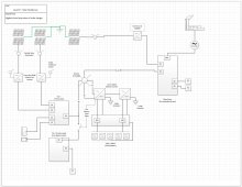
My first attempt at a design - Please note I have done zero math yet although there are a few circuit breaker numbers there, I really didn't put much thought into them. I should probably remove them; but the point is to get an architecture designed and then iterate.

someone could argue to do architecture at an even higher level and maybe that would be worthwhile, but at one level up I might not truly understand how it's supposed to operate and I'm trying to get to a functional understanding. I call those 50,000 foot views "cartoon diagrams".
 

Attachments

  • solardesignv01.JPG
    solardesignv01.JPG
    179.1 KB · Views: 20
AGM, so just custom settings of voltage/current in SI. One of particular note, default max charge rate turns out to be 0.55C of whatever battery capacity we enter, so I reduced that to 0.2C (80A for my 400 Ah battery). If I had 100 Ah per kW of PV as recommended, there would never be too much power available. But because my battery is 1/3 recommended size, my PV could hit 3x the current I want, and default settings would allow that.
I must have you confused with another guy.. now I think I know who. A guy on facebook has the same bat cells I do, but s crap ton more of them.. and like 4 or 6 BMS's.

With AC coupling, it takes several second to do frequency shift and tell Sunny Boys to curtail AC output. I think SI sucks down the excess power during that time and stuffs in into battery. Do you consider that in selecting max battery voltage so it can accept that current without driving BMS to high voltage disconnect?
Nope.. I set my lithium cells to 4.15 volts for disconnect, and 4.0 or 4.1 for max charge.. I do that for reasons concerning battery life, not any sluggishness in the AC coupling.
 
Probably on each new page I should make a THANK YOU post fellas. So, thank you for providing such in depth responses, and thank you in advance for any continued support.
 
@Hedges @MurphyGuy @newbostonconst

My first attempt at a design - Please note I have done zero math yet although there are a few circuit breaker numbers there, I really didn't put much thought into them. I should probably remove them; but the point is to get an architecture designed and then iterate.

someone could argue to do architecture at an even higher level and maybe that would be worthwhile, but at one level up I might not truly understand how it's supposed to operate and I'm trying to get to a functional understanding. I call those 50,000 foot views "cartoon diagrams".

That's fine, but it is my personal opinion that you make one change... When the Sunny Island opens up the load shedding relay, it should cut off everything except life support equipment. Like an oxygen generator for sick grandma..

Why? Because if you allow the Sunny Island to go into a low battery voltage shutdown mode, it won't restart until the battery voltage comes back up.. and how can the battery voltage come back up if the Sunny Islands are shut down?

There is a feature called "Emergency Charge Mode", but trust me, you want to avoid that. The load shedding relay should shed ALL LOADS and stop all battery draining if possible.
See, this is why we make diagrams. ;) To figure out what we misunderstood and to get further clarification. thx.

EDIT: It took a second reading for me to really understand the implications of that. NOW, it makes perfect sense.
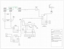
Updated diagram.
 

Attachments

  • solardesignv02.JPG
    solardesignv02.JPG
    184 KB · Views: 16
Last edited:
See, this is why we make diagrams. ;) To figure out what we misunderstood and to get further clarification. thx.

EDIT: It took a second reading for me to really understand the implications of that. NOW, it makes perfect sense.
Updated diagram.
Yeah, regardless of how fancy some of these inverters get, when battery power levels get low, you eventually need to send Scotty down to the engine room to monitor the situation and tell people who's allowed to use power and who's not.
 
Yeah, regardless of how fancy some of these inverters get, when battery power levels get low, you eventually need to send Scotty down to the engine room to monitor the situation and tell people who's allowed to use power and who's not.
Aye, a trekie, awesome. Well, we always need mo' powa Keptain.
 
@Hedges @MurphyGuy @newbostonconst

My first attempt at a design - Please note I have done zero math yet although there are a few circuit breaker numbers there, I really didn't put much thought into them. I should probably remove them; but the point is to get an architecture designed and then iterate.

someone could argue to do architecture at an even higher level and maybe that would be worthwhile, but at one level up I might not truly understand how it's supposed to operate and I'm trying to get to a functional understanding. I call those 50,000 foot views "cartoon diagrams".

"Sunny Boy 6048" - never heard of it, almost thought you meant Sunny Island. Pick a better model number.

The newest Sunny Boys are transformerless (as are some earlier ones.) If using those, make sure your PV panels are "PID free" (really low rate of "potential induced degradation".
Some brands of panels degrade more than others, and some earlier ones quite rapidly. Most panels would ideally be negative ground (all biased positive) to prevent PID. SunPower, made with a different type of silicon for lower light induced degradation, suffered from PID. They had SMA provide inverters which could do positive ground. The newer SunPower panels are supposed to be "PID free".
I'm now using transformer based 5000US series inverters, negative ground for most of my panels and positive ground for SunPower.

As Murphy said, only truly critical loads on breaker panel with Sunny Boys. Assuming Sunny Island with lithium and BMS still has load-shed and shutdown based on battery state of charge, if 10% remains between those settings, calculate inverter no-load consumption plus your critical loads, make sure it will last until sunup. Your 15 kWh lithium battery could have similar usable capacity to my 20 kWh AGM. 10% for you is 1500 Wh. Two SI burn 50W. If sunup is 12 hours away, you've got a budget of 125W, so 75W of other loads would deplete it.

You've got one 60A breaker in main panel feeding SI, and two load panels each with 60A fed by SI.
SMA says 70A max breaker for input. Its maximum draw is 56A. Sizing breaker for 125% of load would be 70A.
SMA says 56A max breaker on output. I've gotta ask the about that, because a thermal breaker should be 125% of load.
Manual for 5048US didn't specify output breaker. I had thought it could handle 56A feed through +40A from inverter (50A for 6048US) but now they want 56A protection.
If you connect load-shed relay and tier-2 panel to a breaker on tier-1 panel, that reduces total breaker rating seen by SI. You'll never pass more than 56A from grid, anyway.

I started with 70A on output, QO270, but resistance difference imbalanced current (only a problem for my 2s2p SI, not for your 2s SI.)
I switched to dual pole 63A Multi 9 from Schneider (which is also thermal-magnetic). Worked fine for 18 months, but suddenly tripped and shut off the house. These were used breakers, and tests I just ran showed 60A (in a cool garage) tripped that one in use but not other spares. So I swapped.
I mean to ask SMA what kind they recommend. I'll probably select a magnetic-hydraulic 60A from Midnight, or from their supplier who has other trip curves. These are supposed to be OK at 100% load, no derating.

"Main Panel, not available off-grid" - put in an interlocked "generator" breaker, and you can manually backfeed from SI. Just turn off the other breaker feeding SI. Turn off excessive loads, of course. Your 3rd Sunny Boy will then be available too (Off-grid, 12kW SI can manage 24kW SB. Although I assume not more than 12kW of load suddenly going offline at any instant.)

Instead of a transfer switch, you could use interlocked breakers to feed Tier-1 and Tier-2 loads from SI vs. main breaker.
Interlocked breakers will enforce "slow", which is good when shifting Sunny Boy from Sunny Island to grid (or SI from grid to generator). Needs a 5 second "off" time, to insure inverter doesn't backfeed out of phase.

Breaker panels which have PV backfeed as well as loads are supposed to comply with "120% rule", also have backfed breakers at far end of panel from main breaker. (doesn't apply to interlocked "generator" breakers.) That is so main plus PV supply don't sum their current and exceed busbar rating.

If your main panel has 200A busbars and 200 A breaker, it is allowed 40A max PV breaker. If it has 225A busbar (like my Square-D QO panel), then 70A PV breaker meets 120% rule.

Same for your critical loads panel with Sunny Boys, regarding busbar, breakers, and breaker location.

Switching UL-1741-SA frequency-watts inverters from SI to grid should be fine, still has anti-islanding and relatively tight voltage/frequency limits.
My older inverters use RS-485 to tell them when to relax to off-grid limits. If I did that switching, I would open a signal relay and interrupt the RS-485. Otherwise, my Sunny Boys wouldn't obey the rules because they think Sunny Island is taking care of that (or has taken them off grid.)

Plan for a tier-3 load-shed. That would be loads like A/C, water heater, dryer.
 
Yeah, regardless of how fancy some of these inverters get, when battery power levels get low, you eventually need to send Scotty down to the engine room to monitor the situation and tell people who's allowed to use power and who's not.
"Sunny Boy 6048" - never heard of it, almost thought you meant Sunny Island. Pick a better model number.

The newest Sunny Boys are transformerless (as are some earlier ones.) If using those, make sure your PV panels are "PID free" (really low rate of "potential induced degradation".
Some brands of panels degrade more than others, and some earlier ones quite rapidly. Most panels would ideally be negative ground (all biased positive) to prevent PID. SunPower, made with a different type of silicon for lower light induced degradation, suffered from PID. They had SMA provide inverters which could do positive ground. The newer SunPower panels are supposed to be "PID free".
I'm now using transformer based 5000US series inverters, negative ground for most of my panels and positive ground for SunPower.

As Murphy said, only truly critical loads on breaker panel with Sunny Boys. Assuming Sunny Island with lithium and BMS still has load-shed and shutdown based on battery state of charge, if 10% remains between those settings, calculate inverter no-load consumption plus your critical loads, make sure it will last until sunup. Your 15 kWh lithium battery could have similar usable capacity to my 20 kWh AGM. 10% for you is 1500 Wh. Two SI burn 50W. If sunup is 12 hours away, you've got a budget of 125W, so 75W of other loads would deplete it.

You've got one 60A breaker in main panel feeding SI, and two load panels each with 60A fed by SI.
SMA says 70A max breaker for input. Its maximum draw is 56A. Sizing breaker for 125% of load would be 70A.
SMA says 56A max breaker on output. I've gotta ask the about that, because a thermal breaker should be 125% of load.
Manual for 5048US didn't specify output breaker. I had thought it could handle 56A feed through +40A from inverter (50A for 6048US) but now they want 56A protection.
If you connect load-shed relay and tier-2 panel to a breaker on tier-1 panel, that reduces total breaker rating seen by SI. You'll never pass more than 56A from grid, anyway.

I started with 70A on output, QO270, but resistance difference imbalanced current (only a problem for my 2s2p SI, not for your 2s SI.)
I switched to dual pole 63A Multi 9 from Schneider (which is also thermal-magnetic). Worked fine for 18 months, but suddenly tripped and shut off the house. These were used breakers, and tests I just ran showed 60A (in a cool garage) tripped that one in use but not other spares. So I swapped.
I mean to ask SMA what kind they recommend. I'll probably select a magnetic-hydraulic 60A from Midnight, or from their supplier who has other trip curves. These are supposed to be OK at 100% load, no derating.

"Main Panel, not available off-grid" - put in an interlocked "generator" breaker, and you can manually backfeed from SI. Just turn off the other breaker feeding SI. Turn off excessive loads, of course. Your 3rd Sunny Boy will then be available too (Off-grid, 12kW SI can manage 24kW SB. Although I assume not more than 12kW of load suddenly going offline at any instant.)

Instead of a transfer switch, you could use interlocked breakers to feed Tier-1 and Tier-2 loads from SI vs. main breaker.
Interlocked breakers will enforce "slow", which is good when shifting Sunny Boy from Sunny Island to grid (or SI from grid to generator). Needs a 5 second "off" time, to insure inverter doesn't backfeed out of phase.

Breaker panels which have PV backfeed as well as loads are supposed to comply with "120% rule", also have backfed breakers at far end of panel from main breaker. (doesn't apply to interlocked "generator" breakers.) That is so main plus PV supply don't sum their current and exceed busbar rating.

If your main panel has 200A busbars and 200 A breaker, it is allowed 40A max PV breaker. If it has 225A busbar (like my Square-D QO panel), then 70A PV breaker meets 120% rule.

Same for your critical loads panel with Sunny Boys, regarding busbar, breakers, and breaker location.

Switching UL-1741-SA frequency-watts inverters from SI to grid should be fine, still has anti-islanding and relatively tight voltage/frequency limits.
My older inverters use RS-485 to tell them when to relax to off-grid limits. If I did that switching, I would open a signal relay and interrupt the RS-485. Otherwise, my Sunny Boys wouldn't obey the rules because they think Sunny Island is taking care of that (or has taken them off grid.)

Plan for a tier-3 load-shed. That would be loads like A/C, water heater, dryer.
Holy cow im drinking from a fire hose. I feel like that freshman in college and I start looking around thinking, I’m gonna have to drop this course.

panel bus bar is 200amp. I did Reflect that one accurately

yes, I rushed my labeling of the SB just to get at least a pic to discuss out there. Will take some More time to get things correct.
cheers
 
@Hedges

if the SI gets connected to the interlock breaker in order to create a micro grid for the grid tie, I’m assuming its connecting via the sunny boy ac port on SI. Won’t there be too much sunny boy generation on that circuit?

im assuming my current micro grid circuit to SI is maxed Otherwise no sense putting anything on the grid side.

what am I missing.

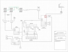
quickly updated the drawing with my interpretation of what you said (just the interlock breaker stuff).
EDIT: 2nd update running interlock back to the SB landing panel.
 

Attachments

  • solardesign03.JPG
    solardesign03.JPG
    183.1 KB · Views: 13
Last edited:
panel bus bar is 200amp. I did Reflect that one accurately

If you want to connect 3x 6kW (or 7.7kW) Sunny Boys backfeeding the grid for net metering, I think an upgrade of main panel will be required for code compliance. Something like a Square-D QO panel with 225A busbar and 150A main breaker would do it, allowing 120A total PV breakers. One 70A breaker for SI, 40A breaker for grid-tie SB.

200A main breaker, 200A panel, 200A busbar? Not 225A rated busbar? Unfortunate.

Don't want busbar to ever carry more than its 200A rating. If PV breakers were placed adjacent to main breaker, 200A main + 60A "Grid Tie SB6048" (you forgot to rename that one) + 60A Sunny Island = 320A

Of course, regardless of breaker rating, will never feed more than inverter output. Possibly 32A from 7.7kW SB, 56A from two SB feeding through SI. That is still 200A + 32A + 56A = 288A

Putting PV breakers at far end of busbar, away from 200A main breaker, there would still be 288A available for loads. But busbar carries 200A in one direction, 88A in other direction from other end. The most current found anywhere in busbar is 200A, and it drops to 200A - 88A = 112A in between. So this way, busbar isn't overloaded.

It would seem 200A main + 200A PV breakers at far end should be OK. But NEC has 120% rule:
200A busbar x 120% = 240A. 240A - 200A main = 40A max total of all PV breakers.
40A x 80% = 32A max continuous load.
32A x 240V = 7680W max inverter output.

This is why there are many brands of 7680W (or 7.7kW) inverters available.

If you just connect SI with 40A breaker, no "Grid Tie SB", system complies. Program SI for 32A max to/from grid. But it doesn't regulate output of the SB it connects to grid, so can only support one SB 7.7kW.

If you connect grid-tie SB with 40A breaker, connect SI with 70A breaker and configure it for "grid charge" (no export), system complies.

There is something called a "line side tap", which means connecting an extra breaker for SB to the wire between utility meter and main breaker panel. Current limits and rules? I'm not sure. It is basically putting two breaker panels on one meter. This can be a way to get around 120% rule, especially for smaller panels like 100A which would have 20A breaker limit.

Another approach is to reduce main breaker. Instead of 200A, if 150A main breaker used, 240A - 150A = 90A PV breaker(s) allowed.

There appear to be ways you can do the install that comply with code's 120% rule, in particular configuring SI to not export. The rule will limit how much PV you can connect, whether you have SI or not. There are "zero export" systems for people without net metering agreement, also "limited export" which could allow 3x SB connected, but limit peak export to what one 40A breaker allows. (for rule compliance, output of 3 SB would have to combine in one panel, then land on main panel through a single 40A breaker and "export" limit to 32A in that breaker.)

It would appear that once system is approved and installed, so long as PV breakers are at far end of busbar, enabling full PV output to backfeed panel and grid wouldn't cause any technical problems. Busbar never carries more than 200A at any point in its cross section. Utility company could observe this with their meter. I can conceive of a way to overheat something (not the panel's "Line" busbar, rather it's "Neutral" busbar.) If I connect the "right" 120V loads, because I'm particularly clever.

So there is code compliance, and there is actual limit of hardware. Main panel upgrade or addition is the proper way to address.
 
@Hedges

if the SI gets connected to the interlock breaker in order to create a micro grid for the grid tie, I’m assuming its connecting via the sunny boy ac port on SI. Won’t there be too much sunny boy generation on that circuit?

im assuming my current micro grid circuit to SI is maxed Otherwise no sense putting anything on the grid side.

what am I missing.

quickly updated the drawing with my interpretation of what you said (just the interlock breaker stuff).
EDIT: 2nd update running interlock back to the SB landing panel.

Yes, backfed interlocked "generator" breaker on main panel is connected to AC1 output of SI.
You can use a 100A or 125A breaker there, assuming suitable wire gauge.
2x SI can deliver 50A (12kW @ 240V) from battery
2x SB can deliver another 50A or so from PV, depending on model.
So a 125A breaker would be ideal.

My setup is like this, but all SB on SI, and 100A "generator" breaker. For now on load shed relay same as your Level-2 panel, but I plan to put it on Level-3 load-shed. Whole house is level-2, garage is level-3.
I'm lucky to have an additional 200A breaker in separate box with meter, so I can do something like line-side tap but with power shut off to do the work. All current limited by breaker at meter, so two panels both with loads won't draw unprotected excess current through the utility drop.

SI has 56A relay; 56A x 240V = 13,440W; that's the maximum SB which can be connected if SI backfeeds grid. So two SB, but not two SB 7.7kW unless their max output is adjusted downward.

If not backfeeding grid, e.g. running off-grid, or generator only, or "Grid Charge", that limit doesn't apply. You may have up to 24kW of GT PV on 2x SI, so your 3rd SB on main panel can be connected.

RTFM:

"14.1.8 Operation Together with PV Inverters and Wind Power Inverters"
"NOTICE
Incorrect plant designs will result in excessive AC power of the PV inverters or wind
power inverters
Damage to the Sunny Island.
• The maximum AC power of the connected PV inverters and the connected wind power
inverters must not exceed 9 kW per SI 4548-US-10 or 12 kW per SI 6048-US-10.
• Observe the following:
PAC max of the PV inverter = 2 x PAC nom of the Sunny Island
PAC max of the wind power inverter = PAC nom of the Sunny Island"

If you had 24kW of SB connected and 24kW of load that suddenly shut off, I don't think it could remain stable. SI has max 140A charge current. At 60V, that is 8400W, so if more than 16.8kW of power disconnected, I don't think 2x SI could suck down the power to batteries for the couple seconds it takes to do frequency shift.
 
200A main breaker, 200A panel, 200A busbar? Not 225A rated busbar? Unfortunate.
ah, might not know what I'm talking about....should have said 200a panel breaker. No idea on the busbar. Will have to figure that out.

I do have a Square D panel 40MW225. So, I'm guessing that means 225a bus bar.
Actually, I have two 40MW225s.

Truly embarrassing that I have an electrical engineering degree. My excuse is I went directly into software development. But...sad really.
 
Last edited:
My EE degree (actually EECS) didn't get into this stuff. It was useful for designing microprocessors at HP.

Most relevant things I learned from an owner-builder class, studying/doing AC wiring projects, grounding/bonding and arc flash/arc blast safety classes at work.

I've been digging into PV and inverters a lot for many years, which is why I'm so much up on this. Plus education and on the job engineering that helps me understand what's under the hood.

Looks like you've got pretty much the ideal main panel.
With 200A main breaker, you're supposed to have no more than 70A total of PV breakers. If you swap it for 150A main then you can have 120A total PV, suitable for your SI and SB.

It appears having all enabled to backfeed and keeping 200A main breaker, while not complying with 120% rule, usually doesn't cause overload. The way I figured out to accomplish it would be large amount of 120V loads only on one phase. With 35kW of 120V loads I could draw 290A on neutral without tripping breakers, from grid and PV.

Maybe codes are there for a reason, but I think even the NEC guys didn't figure this one out. They just threw us a bone with 120% instead of 100% rule, so most consumers could have a reasonable size PV system installed without having to change out their main panel.

If you can get by with 150A main breaker (max 120A continuous load) you should be good.
 
My EE degree (actually EECS) didn't get into this stuff. It was useful for designing microprocessors at HP.
I was EECS or EECE (computer engineering) also; University of Illinoi '86/87 with EECS Masters in Artificial Intelligence (useless) '89.
 
@Hedges - Really embarrassing question, but if I have 2 Square D 40MW225 panels with 200 amp main breaker, does that mean I have 400 amps coming into the house?

The one panel does not feed the other. They both come from the meter.
 
Back
Top