diy solar

diy solar

Small Boat BMS/LFP with backup

rgleason

Small Boat BMS/LFP with Backup
Joined
Jul 3, 2022
Messages
215
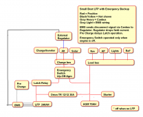
There are many designs based upon preference and existing equipment and space. This is a schematic attempt for a simple and safe system with a SLA battery backup in a small boat (Bristol32) with limited space for much gear. This is definitely not entirely worked out, so comments and suggestions will be appreciated. The goals are as follows:
  1. Safe
  2. Simple
  3. Expect an LFP shutdown sometime, at the worst time.
  4. Seamless use of SLA Battery Backup with no interuption.
  5. SLA Capacity large enough to provide 5 hrs using just critical loads.
Some of the ideas reviewed are from (many thanks):
Cruisers Forum - Lithium Power System Thread
Attainable Cruising - Building a Seamanlike LFP Battery System - John Harries - Hybrid
Nordkyn Design - Lithium Battery Systems - Dual bus - Some design schematics
Some Pictures from my boat upgrade - SVsagres - Hybrid

The note "Pre Charge delays latch operation" is incorrect and should be removed. Wakespeed WS500 and REC BMS are planned. The latch relay may be similar to the Bluesea 7713 that SVsagres used. This schematic has the DC panel connected to a 70A SLA battery which is being charged by the LFP and Alternator through the Orion TR DC-CD 12/12 30A adjustable charger. The Orion is backup spike protection for the alternator in case of an unexpected BMS shutdown. We may use a small adjustable LFP 15A charger (with bluetooth) if available, instead of a bigger Victron Multiplus inverter/charger. We have no 120vac loads and are on a mooring, although if we are connected to shore power, we could plugin the refrigerator, domestic hot water and a few gfi plugs. I still have to figure out where this DC equipment and the batteries can fit inside the cabin.

One of my questions is where the Regulator sense leads should be placed, and how the Wakespeed WS500 will be wired so that it is regulated when only the AGM battery is online. What changes would need to be made?

There very possibly is several levels of backup in the event of failure:
SVsagres wrote: If I get a BMS failure, I can force the system on and limp home (the Wakespeed will go to 13.2v if it doesn't hear from the BMS), but additionally my engine start battery is a basic marine start FLA. The engine itself is basically clockwork (Yanmar 1GM10) so I can go a long time without recharging the start battery. ...If things go bad, I can always manually force the 7713 on with the knob. ..
The BMS is in full control of the charging system, if the rest of the charging system loses contact with the BMS, it goes into a safe mode.
If the WS500 stops receiving CAN messages, it will drop into “limp” mode, setting its voltage limit to 13.2v, which is pretty safe.
So perhaps the AGM would just be charged at 13.2v which really isn't adequate. Your suggestions, comments and experience are welcome.

Small-Boat-LFP-with-Backup.png
 
Last edited:
TAO BMS: How to charge LFP and SLA batteries with an alternator has some good schematics. The last example shows an emergency alternative to power 12v Panel loads from the SLA. One of the differences is the this scheme keeps the lights and nav always on SLA (lead acid). The dynamics of paralleling LFP and SLA are explained well in this page.
 
So in general, your load bus is going to be separate from your charge bus, with its own control from the BMS (no matter whether it's TAO or REC). It's what I've generally referred toa s the "high side" and "low side" of the bus. In my case, the DC load side of the world is connected through a Victron Smart BatteryProtect 60, since my DC loads aren't that big. They also make a 100A and 220A version of it. The BtteryProtect as well is controlled by the BMS (in addition to bluetooth).

As far as the other redundancy goes, I guess it comes down to what are your expected failure modes; what are you protecting against? In normal operation, you should never, ever have a unexpected disconnect of the high side. Assuming your BMS has full control of all your charging sources, they will ramp down their limits as the battery approaches full and/or one of the cells gets out of whack (so the system can balance that cell).

If you're worried about the BMS suddenly failing and letting the high side drop while the alternator is in operation, what I would do is tee off an enable line from the pre-charge circuit to the regulator to shut down the regulator whenever the high side contactor is off.

If you're worried about continuing to operate after your BMS has failed, so you can get home, realize that you can actually run, sub-optimally, without the BMS, but with the LiFePO4 still in operation. As long as I'm not running my inverter/charger, my system is always running at fractional C rates, typically less than 0.05C. It's pretty safe to have that running, at least for a few days, without a functional BMS. This is also true with the Wakespeed. A) in its low current mode, it will only try to drive the battery to 13.2v, which is around 60% charge and B) on my system, at least, I can limit it down to 35A, which is still less than 0.1C into the battery.

I initially looked at doing something similar to what you're doing, with my old 1/2/both switch, but in the end the extra complexity just wasn't worth the extra wiring and terminals/lugs. The only failure I can't get around would be one of the cells themselves, but that's exceedingly unlikely to happen without advance warning, and those kinds of failure modes likely have more severe consequences that the redundancy won't help with (read fire).
 
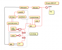
SVsagres I had to draw a schematic of your system so I could better understand what is happening, and attach it here. I am then going to think about it and maybe ask some more questions.

SVsagres.png
 
On the load side the smart battery protect shuts off the panel when necessary to protect the LFP.
On the charge side the Latch switch disconnects the lynx charger bus from the battery on an over charge alert.
All charge devices (solar, alternator and inverter/charger) charge the LFP.
The charging of the start battery is very simple, just a switch.
The alternator is protected by the BMS with a signal to the external regulator WS500.
This is a very simple system.
In my system, the starter batter (a maintenance free marine start battery) is maintained by an orion TR 12/12-18 dc to dc charger. That battery will basically spend its entire life in float.

Both the smartshunt and BMV (used to monitor the starter battery) are completely superfluous, and only there because I’m an instrumentation geek.

The REC has its own shunt that is connected to the negative of the battery.
 
@svsagres Why did you choose the Smart Battery Protect instead of a Latching Switch?
Does it allow better monitoring of the loads? I guess not, because you have a smartshunt doing that. Why is the Smart Battery Protect a better choice than a latching relay in this location?

Got it. You have an Orion TR 12/12 18 DC-DC charging the start battery. I've found that my starter battery with no panel loads on it will last the entire summer without having to be charged. What I have been doing is just charging this Gel cel battery once or twice a summer, on top of that it is about 10 years old and has about 80% capacity. In this configuration, as long as I monitor the battery voltage and keep it charged by turning the switch on for awhile (provided the voltage does not go above 14.1v) it would be fine. During the winter I keep it charged up properly for gelcells. So perhaps no DC-DC is necessary to start with.
 
@svsagres Why did you choose the Smart Battery Protect instead of a Latching Switch?
Does it allow better monitoring of the loads? I guess not, because you have a smartshunt doing that. Why is the Smart Battery Protect a better choice than a latching relay in this location?
Mostly because it's both lower power (only draws a few mA while on), and is significantly cheaper than the latching relay. My DC loads are relatively modest, so I just have the 60A Smart BatteryProtect, which is $68 at fisheries supply. The latching relay off of ebay was around $250.

I would be very careful about just using a switch to charge up the Lead Acid, as your Lithium bank has comparatively infinit current supply capacity. The 18A Orion-TR is $192, a decent switch from BlueSea is around $35, so does save you a few bucks.
 
In my system, the starter batter (a maintenance free marine start battery) is maintained by an orion TR 12/12-18 dc to dc charger. That battery will basically spend its entire life in float.

Both the smartshunt and BMV (used to monitor the starter battery) are completely superfluous, and only there because I’m an instrumentation geek.

The REC has its own shunt that is connected to the negative of the battery.
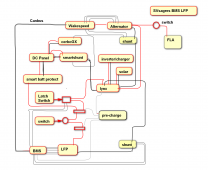
I've tried to add the two shunts, one at the alternator for the wakespeed (I believe), and the other for the BMS. Would these shunts provide information about the alternator current for the wakespeed and the battery current for the BMS?
I am sure the layout of this diagram could be improved substantially and there is no doubt I have shown some things wrong, but this is just a way of communication to understand the system (ie it is not a final wiring diagram - others please note.)

SVsagres.png
 
Mostly because it's both lower power (only draws a few mA while on), and is significantly cheaper than the latching relay. My DC loads are relatively modest, so I just have the 60A Smart BatteryProtect, which is $68 at fisheries supply. The latching relay off of ebay was around $250.

I would be very careful about just using a switch to charge up the Lead Acid, as your Lithium bank has comparatively infinit current supply capacity. The 18A Orion-TR is $192, a decent switch from BlueSea is around $35, so does save you a few bucks.
We have the same DC Panel load situation, being 32' so the 60A BatteryProtect is a good solution.
Thanks for the forewarning about using a good BlueSea switch due to the LFP current capacity, if we have room the 18A Orion TR may be an option.
 
what are your expected failure modes; what are you protecting against?

Normal operation:
You should never, ever have a unexpected disconnect of the high side. Assuming your BMS has full control of all your charging sources, they will ramp down their limits as the battery approaches full and/or one of the cells gets out of whack (so the system can balance that cell).

Sudden BMS Failure:
...and letting the high side drop while the alternator is in operation, what I would do is tee off an enable line from the pre-charge circuit to the regulator to shut down the regulator whenever the high side contactor is off.

Continued Operation after BMS Failure:
.. so you can get home, realize that you can actually run, sub-optimally, without the BMS, but with the LiFePO4 still in operation. ..provided not running inverter/charger, my system is always running at fractional C rates, typically less than 0.05C. It's pretty safe to have that running, at least for a few days, without a functional BMS. This is also true with the Wakespeed. A) in its low current mode, it will only try to drive the battery to 13.2v, which is around 60% charge and B) on my system, at least, I can limit it down to 35A, which is still less than 0.1C into the battery.

Thank you. Now I think I understand the system better, and I think I would install the enable line from pre-charge to protect the alternator.

About continued operation, our bank will probably be about 200ah or about 1/2 your capacity, so the DC Panel is going to be drawing about 0.1C or perhaps a bit more. So you are saying that we could operate the LFP without the BMS , charging to 13.2v with the alternator for a 60% charge, and the alternator could also be limited to a 35A charge, or even some current limit. Note that this would be a bit riskier because the BMS is not available to protect the Reg/Alt and one would want to monitor the system more closely.
It's a bit riskier since it won't take into account cell differences, but the voltage is low enough that assuming you have a reasonably well balanced battery pack, it won't go too far. You're not going to get a disconnect since that has essentially already happened, and you've since overridden it. It's not perfect, and you'll need to keep an eye on things, but good enough to get you home.
 
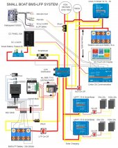
I've tried to make a more detailed diagram, a few things have changed and perhaps I don't have this right. Also I hope I show the CerboGX connections right. I think in the event of a BMS or LFP failure, with this layout two switches will change over from LFP to use the SLA.Small Boat BMS-LFP.drawio.jpg
 

Attachments

  • Small Boat BMS-LFP.drawio.pdf
    7.9 MB · Views: 10
Last edited:
Looks good. Two things:

  1. You should have a Class-T fuse within 6” of the + terminal on your LiFePO4. I’d also do a double MBRF fuse on the + terminal of your SLA, one at 100A or so for your starter motor, the other at 40A (small as you can get) for the Orion-TR. These fuses are there to protect your wiring.
  2. The BatteryProtect should connect to the battery without going through the ML-RBS. The two portions are independent of each other, if you wind up with the ML-RBS dropping due to high voltage (shouldn’t happen) you need your load to run to draw the battery down.
  3. The SmartShunt definitely isn’t absolutely necessary. The REC will do full system monitoring. I just have one because I’m an instrumentation geek, and use it as a DC Energy Meter for my DC loads. I could easily live without it.
 
I'm planning to use the Overkill BMS instead of REC, mostly because it seems a lot simpler. Am I correct that, assuming I can trust the BMS to work properly, it will provide the basic functions of the REC BMS, RBS latching switch, shunt, temp sensor, and Smart Battery Protect?

I understand there are risk/reliability differences between FET and external relay BMS, so I'm not trying to make that comparison here.
What you lose with something like the overkill BMS is the integration possibilities. One of the main selling points of the REC and/or TAO is how tightly they integrate with the Victron environment. In this kind of a design, the BMS itself is controlling the entire charging process, rather than relying on external equipment to accurately set voltages and the like. Furthermore, this control allows it to ramp down, rather than simply cut off once the battery is full.

Furthermore, what do you do if your battery trips out due to high voltage? if all your loads and all your charging are hard wired in, it’s hard to draw the batteries down when everything is disconnected. You’d hve to pull fuses or something to make it work.

So yeah, I’ve gone the fully integrated route, and am very happy with the results.
 
Furthermore, what do you do if your battery trips out due to high voltage? if all your loads and all your charging are hard wired in, it’s hard to draw the batteries down when everything is disconnected. You’d have to pull fuses or something to make it work.

I see. With the external contactor, you can manually connect the battery to loads even if the BMS is unhappy about over-voltage. With a FET BMS in the circuit, we'd need to either change BMS settings by Bluetooth to raise the high voltage cutoff limit, or re-wire something to connect directly to the battery, bypassing the open-circuit BMS.

I get what you mean about integration. There are many ways to skin these cats, and everyone has different choices about what works for them.

Thanks.
 
I'm planning to use the Overkill BMS instead of REC, mostly because it seems a lot simpler. Am I correct that, assuming I can trust the BMS to work properly, it will provide the basic functions of the REC BMS, RBS latching switch, shunt, temp sensor, and Smart Battery Protect?

I understand there are risk/reliability differences between FET and external relay BMS, so I'm not trying to make that comparison here.

I use an Overkill on my boat and am very happy with it. 2 years and over 6,000 ocean miles. This past season I sailed from Virginia to San Francisco. Despite all the scare tactics here, FETS are very reliable, much more so than relays. It's only anecdotal, but I have replaced many more failed relays in my lifetime than FETs, and helped a fellow boater get going again after a relay failed closed and smoked his LFP battery. The Overkill allows all basic functions, cell monitoring via Bluetooth, stopping charging or loads independently(so you can cut off charging without cutting off the loads), SOC meter, current metering, temp sense etc. I do recommend a Victron BVM meter so you can see SOC at a glance of the panel, but that is optional.

My battery has been zero maintenance and 100% reliable. I am not sold on any benefits for a more integrated system. There are a few rare use cases that warrant it, but mostly it adds complexity, more points of failure, and more cost, with no gain in performance of the battery.
 
I see. With the external contactor, you can manually connect the battery to loads even if the BMS is unhappy about over-voltage. With a FET BMS in the circuit, we'd need to either change BMS settings by Bluetooth to raise the high voltage cutoff limit, or re-wire something to connect directly to the battery, bypassing the open-circuit BMS.

I get what you mean about integration. There are many ways to skin these cats, and everyone has different choices about what works for them.

Thanks.
That is NOT how FET based BMS's work. They can still stop charging or the loads independently of each other. The do it on a common bus instead of having a separate charge and load bus, but they still do it. Because there is a common bus, they are much simpler to implement.
 
Back
Top