diy solar

diy solar

Small Boat BMS/LFP with backup

At the end of the day Li is just a battery doing the same thing in a boat as the lead acid did. All we have added is a safety system that acts in “ last moment “ events to protect the battery. Arguably we should have had some of it in LA systems.

Hence I ( and ABYC) don’t require anything else , no complex charge and load bus separation etc.
 
Goboatingnow:
Not suggesting that people don’t do this , what I saying is that fron a basic safety perspective , compliant to ABYC or ISO , there’s no point in dual disconnects( load and charge ) and complex manual overrides and so forth.
Yes but it’s a rare occurrence under normal circumstances. I fail to see the justification for any additional redundancy systems over lead acid. For example if the bms fails you can simply manually override the single bus disconnect breaker
I fail to see the science behind the obsessive system design that inherently assumes regular LVC events
So "the obsessive design" that we are talking about at this point, is to have a single bus, rather than dual bus, which requires removal of:
  • (1) relay coil
  • (2) on-off switches
  • Some cable which you have decided to keep a "jumper cable" while I want it in place with a switch.
Yes, this would reduce cost and be simpler. The occurrence of a BMS shutdown or failure may be "rare" but it is no less dangerous than anything else on a boat.

I think I will make this simplifying change and if ABYC changes, may just add the relay coil and turn it into a dual bus.
The power source for CerboGX and 24/7 items like bilge pumps, etc. needs to be shown.
 
Last edited:
Again , I’m not arguing against complex systems , must people seeing my boat think it’s simply an IT/tech platform ☺️

My point was overly focused systems on an unlikely event are both unnecessary and expensive not to mention complexity for little day to day gain.
 
Goboatingnow:


So "the obsessive design" that we are talking about at this point, is to have a single bus, rather than dual bus, which requires removal of:
  • (1) relay coil
  • (2) on-off switches
  • Some cable which you have decided to keep a "jumper cable" while I want it in place with a switch.
Yes, this would reduce cost and be simpler. The occurrence of a BMS shutdown or failure may be "rare" but it is no less dangerous than anything else on a boat.

I think I will make this simplifying change and if ABYC changes, may just add the relay coil and turn it into a dual bus.
The power source for CerboGX and 24/7 items like bilge pumps, etc. needs to be shown.
I think simplifying to a single all load and charge source disconnect is a good idea , then if needed you can use sequenced load disconnects to prioritise waning battery energy to the important places. Alternatively place your faith in simple SOC alarms that give you warnings in advance of a dead battery
 
@Goboatingnow
Bruce outlined his own “ high end “ solution , nothing wrong with that. With seperate load and charge busses and everything controlled by a CAN bus BMS controlling its charge source.
That’s the Rolls Royce , I drive a Toyota , both take me to the shops safely.
@svsagres has configured the system to control HVD and charging, using
  1. REC BMS canbus with Wakespeed WS550 for separate advance shutdown of Alternator Charging.
  2. REC BMS to CerboGX to control and shutdown charging by the Solar MPPT and Phoenix 120vac charger
Which protects the LFP from HVD High Voltage Disconnect by the BMS. So for the "High Side" we essentially have a Toyota version of a "Top Notch" system.
All we have added is a safety system that acts in “ last moment “ events to protect the battery. Arguably we should have had some of it in LA systems.
Actually, we also have a system that also protects the alternator and electronic equipment from spikes.

@svsagres uses a Mosfet Smart BatteryProtect 65 to protect from LFP LVD low battery protect and discharge.

My diagram, as the system stands now, does not meet the requirement that there is an advance action protecting the battery before the BMS LVD signal releases the relay coil to be "normally open". Of course if I am on the boat I can monitor for discharge and manually disconnect equipment, but if I am not on the boat? Then I must rely on the BMS and the one relay coil. Is this acceptable?

I assume the BMS will have an advance LVD alert, but have not shown it yet.
 
Goboatingnow wrote:
I think simplifying to a single all load and charge source disconnect is a good idea , then if needed you can use sequenced load disconnects to prioritise waning battery energy to the important places. Alternatively place your faith in simple SOC alarms that give you warnings in advance of a dead battery
I see, this done when in Emergency "Limp to harbor" mode.
It might be nice to have some easy way of turning off the chargers (MPPT and Alternator)
 
@Goboatingnow

@svsagres has configured the system to control HVD and charging, using
  1. REC BMS canbus with Wakespeed WS550 for separate advance shutdown of Alternator Charging.
  2. REC BMS to CerboGX to control and shutdown charging by the Solar MPPT and Phoenix 120vac charger
Which protects the LFP from HVD High Voltage Disconnect by the BMS. So for the "High Side" we essentially have a Toyota version of a "Top Notch" system.

Actually, we also have a system that also protects the alternator and electronic equipment from spikes.

@svsagres uses a Mosfet Smart BatteryProtect 65 to protect from LFP LVD low battery protect and discharge.

My diagram, as the system stands now, does not meet the requirement that there is an advance action protecting the battery before the BMS LVD signal releases the relay coil to be "normally open". Of course if I am on the boat I can monitor for discharge and manually disconnect equipment, but if I am not on the boat? Then I must rely on the BMS and the one relay coil. Is this acceptable?

I assume the BMS will have an advance LVD alert, but have not shown it yet.
For me, if I’m not aboard, I put the boat into hibernation mode. That drops my load to 20W or so (Cerbo, Instrumentation, AIS, and LTE left on). With my battery that gives me about 20 days to respond to something gone wrong with charging.

If I’m just leaving the boat for an afternoon, I really don’t care, since I’m fully operational mode (refrigeration, devices, laptops, etc…) I still have about 4 or 5 days until I really need a charge.
 
@Goboatingnow

@svsagres has configured the system to control HVD and charging, using
  1. REC BMS canbus with Wakespeed WS550 for separate advance shutdown of Alternator Charging.
  2. REC BMS to CerboGX to control and shutdown charging by the Solar MPPT and Phoenix 120vac charger
Which protects the LFP from HVD High Voltage Disconnect by the BMS. So for the "High Side" we essentially have a Toyota version of a "Top Notch" system.

Actually, we also have a system that also protects the alternator and electronic equipment from spikes.

@svsagres uses a Mosfet Smart BatteryProtect 65 to protect from LFP LVD low battery protect and discharge.

My diagram, as the system stands now, does not meet the requirement that there is an advance action protecting the battery before the BMS LVD signal releases the relay coil to be "normally open". Of course if I am on the boat I can monitor for discharge and manually disconnect equipment, but if I am not on the boat? Then I must rely on the BMS and the one relay coil. Is this acceptable?

I assume the BMS will have an advance LVD alert, but have not shown it yet.
Have you got an updated diagram
 
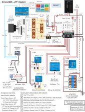
I need to update it, but the most recent diagram (where we are using two relay coils on charge bus and discharge bus).
Will try to update tomorrow.

I thinking about the DC Panel discharging the LFP, for svsagres system diagram, the Smart Battery Protect 65 will provide an advance alarm before LVD shutdown, and will disconnect at 10.5 vdc (or is adjustible). With this system the BMS will simply disconnect the battery from both charging and discharging devices. (after an advance alarm). Which does accomplish the same thing although svsagres system operates the charge and discharge sides separately.
 
Last edited:
Relay Coils further simplified by having just one which disconnects both DC Panel Loads and Charging Devices.
Response to Emergency Shutdown is somewhat modified with just two choices for switching on Bypass Switch A or SLA Switch G.
CerboGX power from SLA battery.

I've also attached a pdf file for better resolution, as done in previous posts.

Simple BMS -LFP Rev 9-07-2022.jpg
 

Attachments

  • Simple BMS -LFP Rev 9-07-2022.pdf
    5.8 MB · Views: 2
I think it’s now an optimum very good system , are you short a terminal in the lynx system so that you could remove the 50A fuse to the DC panel

The only other thing that might be considered is non priority load disconnections under control of the Cerbo
 
Good idea, Lynx has 4 positions and we are only using 3 of them, so that fuse and wire can be moved to the Lynx bus. I'll make that change.

I am considering in the event of a BMS shutdown:
  1. A cheap voltmeter with a momentary contact.
  2. An infrared sensor gun to determine how hot the batteries and connections are.
but you and @svsagres would probably advise that that is needless complication, because you should keep track of the condition and state of the batteries, so you will have an understanding of what the basic problem is because there will be indications of it beforehand. Also all that is required is a multimeter which is more flexible and your nose to smell burning plastic. svsagres advises this will never happen in a properly designed system.

In the situation where there was a HVL we can turn on bypass switch "B" to reconnect the DC Panel and continue to discharge the LFP battery, but we would want to prevent charging, so we would remove the fuses to the MPPT (is this allowed?) and the alternator first. Then we should turn off all non-essential loads a the DC Panel. Is there an easier way to accomplish this?

In the situation where we are approaching LFP LVD but the BMS is not working, we can switch off the main 50 amp DC Panel Breaker. Or switch over to the SLA battery.

In the situation where we need to switch to the emergency SLA battery, keep bypass switch "B" Off and turn On the Emergency Bypass Switch "G".
 
Last edited:
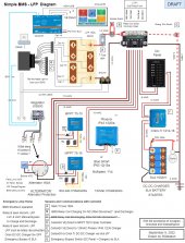
Here is the Sept 9 revised diagram.
Simple BMS -LFP Rev 9-09-2022.jpg
 

Attachments

  • Simple BMS -LFP Rev 9-09-2022.pdf
    5.7 MB · Views: 4
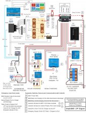
No longer a draft, but still not finished as there will be improvements & clarifications.

Drawio file attached, but remove the ".zip" to use it because .drawio files are not accepted.


Simple BMS -LFP Rev 9-10-2022.jpg
 

Attachments

  • Simple BMS -LFP Rev 9-10-2022.pdf
    5.7 MB · Views: 3
  • Simple BMS -LFP Rev 9-10-2022.drawio.zip
    4.3 MB · Views: 3
Now in my opinion , that diagram is a standard for small boat Li systems , well done
ONly thing that would make it better would be to put the DC loads on their own contactor. but this is an argument that I’ve apparently lost.
 
@svsagres wrote:
Only thing that would make it better would be to put the DC loads on their own contactor. but this is an argument that I’ve apparently lost.
Many thanks go to you for your design and assistance, and if ABYC changes their standard as they learn more, dual bus and double contactors can be easily retrofit!

@Goboatingnow Thank you for sticking with this process and for all your help too. I appreciate the compliment.

@wholybee Thank you for guiding me through all of the inital to mid design. I learned a tremendous amount about Mosfet single bus systems.

Please keep in mind that I am going to have other questions along the way as I try to figure out how to fit this into the boat!
 
Very nice! You have a GREAT system design. I'll probably wind up with something similar to this eventually, as money allows me to by it one piece at a time. My only change would be that there is no manual disconnect, and the Emergency switch allows paralleling of the batteries. So, I would change the emergency switch to a "1-2-off" type between the manual bypass and the lynx distribution.
 
Very nice! You have a GREAT system design. I'll probably wind up with something similar to this eventually, as money allows me to by it one piece at a time. My only change would be that there is no manual disconnect, and the Emergency switch allows paralleling of the batteries. So, I would change the emergency switch to a "1-2-off" type between the manual bypass and the lynx distribution.
Not a bad idea actually , useful interlock
 
@svsagres wrote:

Many thanks go to you for your design and assistance, and if ABYC changes their standard as they learn more, dual bus and double contactors can be easily retrofit!
I do not think dual bus systems , ie CH and DCH buses , despite was Bruce Swarb suggested , will appear In ABYC or the more prescriptive ISO standards simple because both are focused on battery safety first not overall system design. As you easily retrofitted. With you components , ie. REC BMS , you have very fine control over charging limits , especially as you can run DVCC on the Cerbo Gx and Control all Mppt and alternator charge sources , allowing central control What would be nice would to add the ability in the Cerbo to instruct the REC to reconnect the battery , this would even allow remote ( via victron VRM ) ability to reengage charge sources etc. I must study the Ve.can integration of the REC to see what it’s possibilites are
 
Last edited:
Back
Top