diy solar

diy solar

Small Boat BMS/LFP with backup

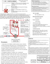
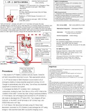
I will add a note to the manual Switch Diagram SK-2, "Engine & Alternator Off when switching".

I think perhaps I should consider powering a few of the essential and low power loads from the SLA in the rare event a BMS/LFP shutdown occurs:
  1. Nav lights (masthead) - separate dedicated switches located on the DC panel
  2. Bilge pumps - separate small panel for fuse and switches
  3. Cabin lights - currently uses DC circuit breaker
  4. Instruments - currently uses DC circuit breaker (also part of nmea2k and nav system)
#1 & #2 could be easily done by connecting to a small 6 fuse panel powered from the SLA.
#3 & #4 are somewhat problematical because the Cabin lights need a switch, and the instruments are really part of the nav system.
Perhaps moving the Cabin lights to SLA are a priority.

Add a note somewhere to disconnect the Solar panels at the M4 connectors before disconnecting from the batteries.
Remember if every wet Wednesday you’re finding you have to switch in the SLA something has gone badly wrong.

Hence given it’s a system only designed to be used occasionally and manually I see no point in spending money to direct the SLA at particular loads. After all you can just selectively trip them out manually at the panel.

Hence just power up the boat completely from the SLA. This is the simplest electrically.

Then depending on whether you are facing a long period of “ bypass” or a short period you can decide to selectively manually kill certain loads.

It’s a mistake to complex engineer a costly system that almost never gets used.
 
Post #4 and #5 by Benv from offgridsolar.com forum REC-BMS and WS500 Smart Regulator Users forum.
He makes some observations about the diagram.
I have added a few revisions to the list #380

Also re Wakespeed WS500 new developments Sept 14 2022.
I found the new Victron documentation for Wakespeed WS500 and it is showing a separate current shunt in the Alternator red cable to the Lynx bus. The temp sensor goes on the alternator and it does appear we should use VE.bus. Also now has alternator voltage, current and temp on the VRM portal.

Why the red cable? Can't we use the same shunt as the REC Active BMS which is closer to the battery and on the black cable?


From Wakespeed WS500 Technical Docs
Remote sensing / Port Expander: The WS500 Alternator Regulator is able to take advantage of the CAN communications capability to transfer real-time battery status: voltage, amperage, and temperature as well as operational status (e.g., off-line in the case of a LiFeP04). By using this capability wiring and installations may be simplified.

Self healing / fail over: Ability to self-recover from a failed, removed, or turned off device. The system continuously monitors all devices and adjusts as needed.

‘Get-Home’ total system failure mode: In the event of a catastrophic total system communications failures, the WS500 Alternator Regulator will fail-to-safe and operate in a stand-alone mode. Allowing for continued charging, but perhaps with less optimization and longer times needed

WS500 and REC BMS use SMA: The ‘Sunny’ SMA CAN protocol an 11-bit message commonly used in the Solar and Electric Vehicle industry. It allows for a BMS to tell charging sources to start, stop, and which goals to utilize. Often know as the SMA protocol, it is also reflective of the Victron 11-bit BMS protocol, though at a different CAN speed

WS500 has the ability to manage an optional external DC-DC converter and control the transfer of power between two separate DC busses. Page 69
WS500 User Manual has a wiring diagram on page 8 showing the shunt on the negative, so I believe the REC BMS and WS500 can share that shunt.

WS500 with REC BMS Active and Q Pdf
 
Last edited:
After my comment:
I note that Bruce Schwab, who prefers dual bus configurations, hopes that ABYC will evolve to support separate shutdown of the charge bus and discharge bus.
John Harries "Attainable Adventure Cruising" thread "Seamanlike Lithium Battery System" reports:
Hi Rick,
I’m sure he does, me too!
Just read the standard and you are right:

13.7.2.1A BMS shall respond to any conditions outside the SOE by activating the output disconnect device.

My guess is that this is probably the result of poor drafting, rather than intended. The problem, of course, is the word output.
Just another way in which ABYC E13 is, in my view, deeply flawed.
All the said, if it were me I would consider installing an all Victron or Lithionics system with duel busses and then hide behind:

13.6.1.2 No electrical connections shall be made directly to a battery that would bypass a BMS or any battery protection circuits. EXCEPTION: Connections made specifically per the battery manufacturer’s instructions.

(As I remember Victron manuals for their higher end BMSs show duel busses, so I would file that and feel comfortable.
Anyway, I’m 100% with Stein on this, in my view, compelling the BMS to dump the loads just because of an overcharge does not increase safety, it decreases it since load dumps are dangerous in and of themselves and overcharge is the most likely scenario to cause a disconnect.

My response to him:
I actually agree, but am trying to keep it really simple and follow ABYC requirements. REC BMS Active supports dual bus and several additional relays and integrates well with WS500 and CerboGX via VE.CAN and Canbus. So what would it cost for dual bus? Another relay?

Although dual bus increases cost somewhat there are many advantages to a dual bus that works as one would expect,
A. Disconnecting the charge bus on HVE ,
B. Disconnecting the discharge or load bus on LVE.

The lights won’t go out on “A” as the loads reduce the battery SOC,
and for "B" the alternator and chargers remain connected to recharge the LFP.

Also I am planning a rather small LFP 240-300ah, not having the additional small load of the NO relay does help, although our 100w solar would help, when we aren’t on board and on the mooring.

Thanks for checking.
 
Last edited:
Also re Wakespeed WS500 new developments Sept 14 2022.
I found the new Victron documentation for Wakespeed WS500 and it is showing a separate current shunt in the Alternator red cable to the Lynx bus. The temp sensor goes on the alternator and it does appear we should use VE.bus. Also now has alternator voltage, current and temp on the VRM portal.

It’s on the VE.Can interface, not VE.Bus. (I have this setup working for a couple months now). VE.Bus is an older RS485 based bus, primarily used by Victron for communicating with their Multiplus inverter/chargers and related equipment. VE.Bus isn’t relevant to your configuration as you don’t have a multiplus. I also have this tied into my NMEA 2000 network, as it puts all the information from my power system and engine (thanks to the ws500) onto the N2K bus for my instrumentation.

At the same time, it also lets me see all my boat’s instrumentation remotely, and also export it via signal-k to my phone, watch, etc… Having a live readout of the depth sounder on my apple watch, while up on the foredeck and prepping to drop anchor is remarkably handy. Conversely, it’s great to be able to look at all of that stuff quickly from my phone while in my bunk for the piece of mind of knowing I haven’t moved, and that I have enough depth under the keel.

Why the red cable? Can't we use the same shunt as the REC Active BMS which is closer to the battery and on the black cable?

The point is to measure the alternator current independently. I‘m using an old shunt left over from my Link 10 battery monitor that has long since died. In my case, though, since my alternator is isolated ground, I actually have it on the low side of the alternator rather than the high side. However, the electronics in the WS500 can also handle a high-side shunt which is nice, given that most alternators are not isolated ground.

From Wakespeed WS500 Technical Docs


WS500 has the ability to manage an optional external DC-DC converter and control the transfer of power between two separate DC busses. Page 69
WS500 User Manual has a wiring diagram on page 8 showing the shunt on the negative, so I believe the REC BMS and WS500 can share that shunt.

WS500 with REC BMS Active and Q Pdf
They can, but you’re better off, in my opinion, to be able to know the actual current out of the alternator, rather than the net in/out of the battery. When building your wakespeed configuration, it’s the difference between “shunt at battery” and “Shunt at alt” in the appropriate command string.
 
13.6.1.2 No electrical connections shall be made directly to a battery that would bypass a BMS or any battery protection circuits. EXCEPTION: Connections made specifically per the battery manufacturer’s instructions.

(As I remember Victron manuals for their higher end BMSs show duel busses, so I would file that and feel comfortable.
Anyway, I’m 100% with Stein on this, in my view, compelling the BMS to dump the loads just because of an overcharge does not increase safety, it decreases it since load dumps are dangerous in and of themselves and overcharge is the most likely scenario to cause a disconnect.

My response to him:
I actually agree, but am trying to keep it really simple and follow ABYC requirements. REC BMS Active supports dual bus and several additional relays and integrates well with WS500 and CerboGX via VE.CAN and Canbus. So what would it cost for dual bus? Another relay?

Although dual bus increases cost somewhat there are many advantages to a dual bus that works as one would expect,
A. Disconnecting the charge bus on HVE ,
B. Disconnecting the discharge or load bus on LVE

I could not disagree more with this philosophy

Since HVE and LVE are critical safety trips I would not condone leaving anything connected after a trip. Loads and charge sources should be disconnected.

Manual inspection will then occur and then and only then can either selective loads or charge sources be manually reinstated.

A bms does not know “ WHY “ a HVE , or an LVE occurred. it should not make connection decisions based on not knowing what Is wrong.

People need to stop seeing LVE or HVE as somehow “ normal “ and that the battery system remains operational at such events.

In particular reconnecting charge sources on lve is inherently dangerous and never occur automatically.
 
Last edited:
I could not disagree more with this philosophy

Since HVE and LVE are critical safety trips I would not condone leaving anything connected after a trip. Loads and charge sources should be disconnected.

Manual inspection will then occur and then and only then can either selective loads or charge sources be manually reinstated.

A bms does not know “ WHY “ a HVE , or an LVE occurred. it should not make connection decisions based on not knowing what Is wrong.

People need to stop seeing LVE or HVE as somehow “ normal “ and that the battery system remains operational at such events.

In particular reconnecting charge sources on lve is inherently dangerous and never occur automatically.

There is a slow learner here, forgive me. Your explanation is good. It is the reason we have a single relay.
I suppose that the second relay and bus only offer the advantage, after manual inspection, of connecting the charge bus to recharge a LVE or connecting the load bus to deplete an HVE.

After a BMS/LFP failure and shutdown:
  1. Manual inspection to determine the problem. The BMS will still have power. The CerboGX is powered from SLA so provided the SLA is not dead, it will still work.
  2. LVE determined. Switch off the main DC Panel breaker.
  3. HVE determined. Switch off the chargers use the on/off terminals of the MPPT and a field wire switch for the Alternator?
  4. These would all have to be set properly before moving the switch from LFP Disconnect & SLA Emergency to LFP Override to recover the LFP Battery and BMS.
 
Last edited:
It’s on the VE.Can interface, not VE.Bus. (I have this setup working for a couple months now). VE.Bus is an older RS485 based bus, primarily used by Victron for communicating with their Multiplus inverter/chargers and related equipment. VE.Bus isn’t relevant to your configuration as you don’t have a multiplus. I also have this tied into my NMEA 2000 network, as it puts all the information from my power system and engine (thanks to the ws500) onto the N2K bus for my instrumentation.

At the same time, it also lets me see all my boat’s instrumentation remotely, and also export it via signal-k to my phone, watch, etc… Having a live readout of the depth sounder on my apple watch, while up on the foredeck and prepping to drop anchor is remarkably handy. Conversely, it’s great to be able to look at all of that stuff quickly from my phone while in my bunk for the piece of mind of knowing I haven’t moved, and that I have enough depth under the keel.


The point is to measure the alternator current independently. I‘m using an old shunt left over from my Link 10 battery monitor that has long since died. In my case, though, since my alternator is isolated ground, I actually have it on the low side of the alternator rather than the high side. However, the electronics in the WS500 can also handle a high-side shunt which is nice, given that most alternators are not isolated ground.


They can, but you’re better off, in my opinion, to be able to know the actual current out of the alternator, rather than the net in/out of the battery. When building your wakespeed configuration, it’s the difference between “shunt at battery” and “Shunt at alt” in the appropriate command string.
I also have a failed Link10 right now . I could use that shunt for the alternator, in the black neg line to the Lynx bus, for "shunt at alt" setting. I believe my converted to external regulator Delco Remy SI28 12V 160A that I am going to field limit to 100a is not isolated ground. Thanks.

Will change to VE.CAN
 
Revision 10-2-2022
See Post #380 Diagram Changes to make
I have two open questions that I know of:
1. Have I shown the REC BMS VE.CAN and WS500 VE.CAN correctly?
2. At the starter battery, do I need an on/off switch between the battery and the bus bar? If so, would a 250A mbta suffice?

I am hoping that I am almost finished with this!
I need to complete the list of equipment.

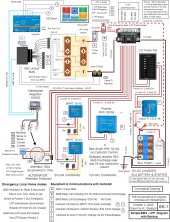
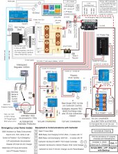
Simple BMS -LFP Rev 10-2-2022-SK-1.jpgSimple BMS -LFP Rev 10-2-2022-SK-2.jpg
 

Attachments

  • Simple BMS -LFP Rev 10-2-2022.zip
    4 MB · Views: 3
  • Simple BMS -LFP Rev 10-2-2022.pdf
    7.1 MB · Views: 4
Offgridsolutions Post #8 Benv

ISO TE13: NOTES: If batteries are paralleled in an unbalanced state, extremely high paralleling currents can flow. If used automatic paralleling devised or on/of switches, should have an appropriate current limiting capability.
Manual switch 1, 2 both and automatic parallel systems MAY NOT BE appropriate.
(Rick) Is the last line above actually Ben's comment?

Ben then wrote:
As example, your starter battery is empty and you use the "emergency switch" is good to know that the amp limiting from the resistant in the cable is enough, to not blow the fuses.
That why I wrote do some tests.
I am trying to understand why this is necessary if we are not paralleling the batteries? Does he not understand it?
 
There is a slow learner here, forgive me. Your explanation is good. It is the reason we have a single relay.
I suppose that the second relay and bus only offer the advantage, after manual inspection, of connecting the charge bus to recharge a LVE or connecting the load bus to deplete an HVE.

After a BMS/LFP failure and shutdown:
  1. Manual inspection to determine the problem. The BMS will still have power. The CerboGX is powered from SLA so provided the SLA is not dead, it will still work.
  2. LVE determined. Switch off the main DC Panel breaker.
  3. HVE determined. Switch off the chargers use the on/off terminals of the MPPT and a field wire switch for the Alternator?
  4. These would all have to be set properly before moving the switch from LFP Disconnect & SLA Emergency to LFP Override to recover the LFP Battery and BMS.
Again the Victron mppt has Bluetooth on off so you can disable charge via this of using the Cerbo or using the remote on off. It’s up to you.

Again yes if you want a CH and a DCH bus great use two contactors but the bms should kill both in lve and hve
 
Ok, is that in case relay contact weld, for example.
Would the disconnect be between the LFP and relay?

Should I also have one at the SLA?
 
Ok, is that in case relay contact weld, for example.
Would the disconnect be between the LFP and relay?

Should I also have one at the SLA?
I would always reccomend a simple single pole switch before the bms contactor and yes also on the SLA output.

In things like fire , or other emergencies you just want to kill the batteries. Also useful where you need to work upstream and want the security of an electrically dead system.
 
I would always reccomend a simple single pole switch before the bms contactor and yes also on the SLA output.

In things like fire , or other emergencies you just want to kill the batteries. Also useful where you need to work upstream and want the security of an electrically dead system.
Yep, this is something I've brought up before... on both my batteries, I have a full disconnect. On my LFP, it goes Battery+ -> Class-T Fuse -> Disconnect -> Unswitched positive bus (which in turn feeds my load and charge contactors). If I want to kill the system dead, to work on it, say changing the class t, or re-working the wiring, I can fully disconnect the battery manually.

One of the key safety things, though, is that I have my wiring laid out such that there is no way the unfused heavy wires from the + of the battery can physically reach anything connected to the negative bus. It's all kept deliberately short.

On the Lead Acid Starter side of my system, I also have a main battery disconnect primarily so that I can kill my engine dead. This is both theft protection, and safety when working on the engine. It's not full lockout/tagout (as you can't lock the Blue Sea 6006), but its good enough for my purposes.

With both disconnects open, the only thing that will remain powered on in the system is the BMS on the LFP, and the monitor on my starter battery. Everything else is completely dead.
 
Revision 10-2-2022
See Post #380 Diagram Changes to make
I have two open questions that I know of:
1. Have I shown the REC BMS VE.CAN and WS500 VE.CAN correctly?
2. At the starter battery, do I need an on/off switch between the battery and the bus bar? If so, would a 250A mbta suffice?

I am hoping that I am almost finished with this!
I need to complete the list of equipment.

View attachment 114564View attachment 114565
Very minor correction, you'll want to move the alternator shunt to the positive (B+) side of the alternator, as your alternator isn't an isolated return model. WS500 is fine with a high side shunt. Also, because the REC is designed for dual channel operation, if you want to run it with a single contactor, you'll need to wire both CH and DCH relays outputs in series to make a "Wired AND" circuit. The BMS really is intended for dual bus operation.
 
Very minor correction, you'll want to move the alternator shunt to the positive (B+) side of the alternator, as your alternator isn't an isolated return model. WS500 is fine with a high side shunt. Also, because the REC is designed for dual channel operation, if you want to run it with a single contactor, you'll need to wire both CH and DCH relays outputs in series to make a "Wired AND" circuit. The BMS really is intended for dual bus operation.
Thanks I was wondering about the BMS relays, thats a good solution.

On the diagram will note the alternator Delco Remy 28SI 12v 160a #360312 - dual fan, negative ground, J180 short hinge mount, rotation clockwise, temp rating 125°C / 257°F, 10000 rpm continuous. Modified for external regulator. It just has a ground screw on the casing so it is not isolated ground.
 
Last edited:
Post #93 Summary ABYC and Major Requirements

Post #247

Post #280

See Post #383 John Harries checked, a response to Bruce Schwab's...

See Post #383 John Harries wrote: All that said, if it were me I would consider installing an all Victron or Lithionics system with duel busses and then hide behind:

Post #261

Offgridsolutions Post #10 Benv Comments


Post #256


Post #390 Goboatingnow


Post #242 Panbo identification of ABYC E-13 items:


Post CF #65


Post #349 and Post #340


CF Post #48
Originally Posted by s/v Jedi View Post

Goboatingnow wrote:


Post #339

Post #160

Post #92

Post #141

Summary ABYC and Major Requirements - continued from Post #378
We've run out of space for adding to this reply, so I've added another reply in order to continue.

Offgridsoftwaresolutions.com Post #11 by @Goboatingnow
One point I feel very excercised on and I see it pop up across many forums

HVE and LVE should be configured to be serious safety trip points and if they occur should be treated so. Both should NEVER occur in a properly functioning Li system. Low SOC alarms should trigger well before LVE and charge stop should occur well below HVE

Hence consistent with ABYC and ISO I would argue on these events the battery is disconnected from all load and charge sources.

Then after manual inspection and cause determination should the appropriate overrides be activated which can (a) switch in alternative power sources (b) reconnect charge sources ( c) reconnect loads.

A bms should NEVER decide to allow charge sources to remain connected on LVE or loads on HVE. The BMS HAS NO IDEA what caused the lve or hve and hence to have it leave charge sources or loads connected on any combination of these safety trips is not “ safety first. “

We must get away from the false notion that LVE or HVE are benign common situations in a normal system. They are not . On HVE LVE over temp and over current which all result in complete LI disconnect, no automatic re connection should occur without manual inspection and then manual intervention process depending on what’s discovered.
For me, a definitive statement that should dispel any of my wayward ideas. Thank you.
 
Last edited:
Summary ABYC and Major Requirements - continued from Post #378
We've run out of space for adding to this reply, so I've added another reply in order to continue.

Offgridsoftwaresolutions.com Post #11 by @Goboatingnow

For me, a definitive statement that should dispel and of my wayward ideas. Thank you.
Forgive me if I come across as “ prescriptive “ but I feel the whole point of ABYC and ISO and also a safety first perspective should pertain , and that everything else should fall in line
 
Revision 10-3-2022 adding disconnects at both batteries, moving alternator shunt to positive.
Hopefully this is 98% complete. Thank you Goboatingnow, svsagres and wholybee. I could not have gotten this far without all your help! It is a great feeling to have some confidence about this diagram due help from to my excellent teachers!

Simple BMS -LFP Rev 10-3-2022-SK-1.jpgSimple BMS -LFP Rev 10-3-2022-SK-2.jpg
 

Attachments

  • Simple BMS -LFP Rev 10-3-2022.pdf
    7.6 MB · Views: 3
  • Simple BMS -LFP Rev 10-3-2022.zip
    4.5 MB · Views: 3
Back
Top