diy solar

diy solar

Small Boat BMS/LFP with backup

to broaden the discussion also as you need to look at industrial equipment rather then marine branded gear

for other components I have one of these on order https://www.connectorconcepts.com/lare12.html as the bi-stable relay has little current , but the issue is how to make it " fail safe "

as I have used Te connectivity 2219561-1 500A EV relays but these have a 600mA operating current ( which I drop to 300mA after initial pullin ) these are nice because they can fail open when the power fails

I have a design for a very rugged MOSFET using STY145N65M5 Mosfets ( 650V 138 A) switch that I will build later in the year but component availability is killing me right now
 
Last edited:
Following with great interest. With respect to the BMS's, the choices I've so far considered are the Rec, Tao and Batterybalance. The Tao unavailable until possibly October/November and I haven't found any reviews or comments on the Batterybalance. It would seem they are all up there price wise when you add all the bits and pieces but to go this route (ABYC compliant) the difference is not so bad. I suspect the Batterybalance would not be compliant with the way the LA and Li systems are connected but this could possibly just not be connected. Are there any other BMS's I should consider? Boat is on the hard in Cartagena right now and we'll be down there November to hopefully install the lithium.
 
I like The REC units, I reread the manual and dont see where it supports pre-qualifying charge . The touble being that no marine chargers I know of are so equipped and there s no way to trigger a prequalfying charge cycle ( typically cell at 2.14V and then charge is <1/10-1/20 C)

personally I see no advantage in leaving the bilge pumps connected around the BMS , The battery is close to discharged when the BMS triggers anyway , then the bilge pump's will flatten and ruin your Li bank , a better way would be a dedicated LA battery for the pumps, fed by a DC DC from the Li !!!

ISO aludes this
4.5 Consideration should be given to providing power for critical systems (e.g., engine starting, navigation lights, etc.) if a BMS shuts down the battery.

Certainly if you leave this setup as is, do not activate recharging automatically after LVC disconnect


well if does if you configure one of its digital inputs to do so ( Im very familiar with the wakespeed as its the VSR open source project turned commercial and I have built the VSR units )
In this case, precharge refers to what’s done to the power bus before the contactor is closed. The inverter/chargers have (very) large capacitors on their inputs. Simply closing the contactor will result in a large inrush current for a brief period. The precharge box initially connects a 20ohm power resistor across the contactor to allow the voltage to come up slowly, then after a delay, closes the contactor. Victron’s Lynx BMS has similar functionality integrated, but it’sa little more sophisticated in that it watches to make sure the voltage comes up sufficiently before closing the contactor. The REC unit just has a fixed delay.

As far as my bilge pumps go, I keep a tight ship, so in general they don’t do anything (I have monitors to keep an eye on them). However if there is a reason for them to keep running, it means that there is a serious leak, and I’m more than happy to sacrifice the battery to keep the boat afloat.
 
In this case, precharge refers to what’s done to the power bus before the contactor is closed. The inverter/chargers have (very) large capacitors on their inputs. Simply closing the contactor will result in a large inrush current for a brief period. The precharge box initially connects a 20ohm power resistor across the contactor to allow the voltage to come up slowly, then after a delay, closes the contactor. Victron’s Lynx BMS has similar functionality integrated, but it’sa little more sophisticated in that it watches to make sure the voltage comes up sufficiently before closing the contactor. The REC unit just has a fixed delay.
oh I see , inrush preventers , mind you for Li installs a small 1/20C mains charger would be very useful to bring very dead LI banks back and act as a pre-qualifying charger
As far as my bilge pumps go, I keep a tight ship, so in general they don’t do anything (I have monitors to keep an eye on them). However if there is a reason for them to keep running, it means that there is a serious leak, and I’m more than happy to sacrifice the battery to keep the boat afloat.
well its a length of string , (a) you could just equally end up with a sunk boat AND ruined Li (b) start the crash pumps just as the Li is runed but the boat is saved or (c) your cellular altering system warns you well in advance !!!
 
I'm planning to use the Overkill BMS instead of REC, mostly because it seems a lot simpler. Am I correct that, assuming I can trust the BMS to work properly, it will provide the basic functions of the REC BMS, RBS latching switch, shunt, temp sensor, and Smart Battery Protect?

I understand there are risk/reliability differences between FET and external relay BMS, so I'm not trying to make that comparison here.
@madmike

I have looked through Overkill Solar BMS and while it has very good instructions, and looks like an excellent BMS, providing all the features one would want for LFP, I do not believe it will take the place of REC BMS or TAO BMS, because it will not interface with the Wakespeed WS500 and does not provide an advanced alarm before shutdown as required by ABYC.

@svsagres advised
What you lose with something like the overkill BMS is the integration possibilities. One of the main selling points of the REC and/or TAO is how tightly they integrate with the Victron environment. In this kind of a design, the BMS itself is controlling the entire charging process, rather than relying on external equipment to accurately set voltages and the like. Furthermore, this control allows it to ramp down, rather than simply cut off once the battery is full.

Furthermore, what do you do if your battery trips out due to high voltage? if all your loads and all your charging are hard wired in, it’s hard to draw the batteries down when everything is disconnected. You’d hve to pull fuses or something to make it work.

@madmike advised
With the external contactor, you can manually connect the battery to loads even if the BMS is unhappy about over-voltage. With a FET BMS in the circuit, we'd need to either change BMS settings by Bluetooth to raise the high voltage cutoff limit, or re-wire something to connect directly to the battery, bypassing the open-circuit BMS.

I get what you mean about integration. There are many ways to skin these cats, and everyone has different choices about what works for them.
@wholybee advises that he uses the Overkill BMS for the last 2 years
See his Post #17
I use an Overkill on my boat and am very happy with it. 2 years and over 6,000 ocean miles. .. [confidence in FETs] ... The Overkill allows all basic functions, cell monitoring via Bluetooth, stopping charging or loads independently(so you can cut off charging without cutting off the loads), SOC meter, current metering, temp sense etc. I do recommend a Victron BVM meter so you can see SOC at a glance of the panel, but that is optional.

My battery has been zero maintenance and 100% reliable. I am not sold on any benefits for a more integrated system. There are a few rare use cases that warrant it, but mostly it adds complexity, more points of failure, and more cost, with no gain in performance of the battery.

The Overkill BMS seems to be very well engineered, documented, well regarded and is on github.com Overkill Solar 4s BMS 120a LifePo4 with 12″ 8ga Wires is about $150.

I notice in the manual that the discharge FET can be disabled, but it does not look like a latching relay can then be used. I wonder this BMS could be improved such that the charge FET could be a latching relay too, so we could signal the Wakespeed to turn off field current, then send an shutdown alert as required by ABYC , and then delay shutdown of the LFP by say 15-30 seconds?

3.4.1 Switch When enabled, the discharge FET will be disabled when the optional external switch contact is open. ...

It looks like I am going to need to use the REC BMS....
 
Last edited:
svsagres outlines all the parts for his system in this post in another thread because I am very interested in this system. I am going to copy his list here.
  • REC Active BMS (Victron/Wakespeed Version)
    • 500A shunt
    • Variable Pre-Charge Unit
    • REC software/RS485 cable (not strictly needed, but nice to have)
  • Battery itself is a 2p4s 460AHr pack, built with 230AHr EVE cells
  • Victron Smart BatteryProtect 65 (Low Voltage Disconnect, controlled by REC)
  • Blue Sea Systems 7713 500A bi-stable relay (High side disconnect)
    • This is actually a little more difficult to interface then I originally thought, and I partially regret buying it
  • Wakespeed WS500 Alternator Regulator
    • Controlling a Hitachi 80A alternator until we re-power with a new engine
  • Victron Multiplus Compact 12/2000-80 Inverter/Charger
  • Victron Cerbo GX
    • Core piece that interconnects the Inverter/Charger to the BMS/Alternator
  • Victron Orion-Tr 18A DC:DC charger
    • Maintains the starter battery (A simple Group 24 Marine Start battery)
  • Victron 75/15 MPPT controller
    • Power from 2x 60W 24V solar panels
    • Just enough power to keep the parasitic loads of the monitoring system live if shore power disconnects
Then, because I'm a system integration geek who likes his toys, I have the following extras:


  • Victron Smart Shunt
    • Monitors the house loads
  • Victron BMV-712
    • Monitors the starter battery
    • Relay used to turn the Orion-Tr on and off
  • Netgear M1 Nighthawk LTE router
    • Allows VRM monitoring and remote control of the Cerbo GX over the internet
We're investigating how to remotely control the REC, but I think we can do it from Node Red on the Cerbo (essentially reconfiguring the REC on the fly) to achieve the target SOC of around 70% while the boat is at the dock and just in use for day sailing. The idea is to be able to flip it to 100% the day before we head out for a multi-day trip. Also, I'm probably going to use Node Red to control the Orion, as its alternator detection probably won't work too well the flat charge curve on the Lithium house bank.

Lastly, this will all be tied into our NMEA 2000 network, so I'll probably wind up running SignalK on the Cerbo as well, exporting all the nav data via wifi to my various devices.

@svsagres wrote: ...and I wonder what the problem was and if he would do something differently now?
  • Blue Sea Systems 7713 500A bi-stable relay (High side disconnect)
    • This is actually a little more difficult to interface then I originally thought, and I partially regret buying it

I found this "Filterguy" resource Beginners Summary of BMS Functions, Types and Features 2021-04-11 very helpful.
There are other good documents DC Fusing and breaker Size and Placement
The "Filterguy" full list in this post #2
 
Last edited:
@svsagres wrote: ...and I wonder what the problem was and if he would do something differently now?
The issue was mostly integrating it with the pre-charge circuit. As it turns out, the transistor circuit I posted elsewhere has been reliable, so it’s all good.
 
Control of all charge devices to conform to LFP SOC

Ideally all chargers should be actively managed by the BMS which knows the LFP state of charge SOC, if this cannot or is not possible, their charge parameters must be set to shut charging off in advance of the LFP charging limit so that the BMS does not activate disconnection (and in reverse for discharging).

With multiple charge sources like shore power 120vac charger, alternator and multiple MPPT solar, all actively filling an empty battery, they should all be regulated so the LFP battery is not overcharged or depleted.

How to accomplish this?

Gathering Information...

Regarding the planned two Smart MPPT Solar Chargers and ".. multiple charge sources charging a single battery bank" blog by Peter Kennedy.

Victron has NETWORKED CHARGING for multiple MPPT
  • The latest version of the Victron Connect app allows you to network together multiple solar charge controllers so they all work in unison. The procedure is explained in the Victron Connect Smart Networking Manual
  • This is achieved automatically when you set up the smart network. One MPPT is selected automatically as the Master and the slaves all follow.
  • Battery Temperature is Externally via the Smart Battery Sense (only SmartSolar models).
  • Battery Voltage, Current and State are provided by the MPPT and shown in Victron Connect.
In the Color Control GX there is some information about SOC that is relevant to SOC and equipment.
  • Using a Multiplus
  • No battery monitor is required, as long as all MPPT Solar Chargers are Victron products and are connected to the CCGX . The CCGX will continuously read the actual charge current from all solar chargers, and send the total to the Multi (or Quattro) which then uses that information in its SOC calculations.
This document continues and answers the question, because we do have DC-DC chargers and Alternator! And hope to have a small AC Charger. Victron suggests installing a BMV or Lynx Shunt VE.Can.
When there are more chargers, or loads, connected to the battery than just the Multi or MPPT Solar Chargers, a dedicated Battery Monitor will be required. Examples are:
  • House loads in Marine or Vehicle system.
  • PWM Solar Chargers
  • AC chargers, such as Skylla-is, Phoenix chargers, non Victron chargers, etc.
  • Alternators
  • DC-DC chargers
  • Wind turbines
  • Hydro turbines
In case a battery with built-in monitor is used, such as explained in (C), then that is the dedicated battery Monitor. Refer to section (C).
Otherwise, install a BMV or Lynx Shunt VE.Can.

Also in the ESS documentation it appears that Multi Inverter/Chargers have a built in battery monitor that can be used, but since we aren't going to have one of those, it is not available.
The built-in battery monitor of the Multi Inverter/Charger can be used to provide data where installed batteries do not have a
monitor built-in. The advantage here is that in an ESS system the charge currents from MPPT Solar Chargers will also be taken
into account.

Using the Victron SmartShunt or BMV as a DC Ammeter blog by Peter Kennedy
Additionally, the BMV 712 Smart with a shunt, measures SOC of a LFP and will control relays for High/low SOC, high/low voltage, high/low mid voltage, high/low starter also there is an alarm buzzer for all of these conditions.

Also Peter advises on the advantages of adding a BMV 712 Smart, with shunt, to Smart MPPT Solar chargers.
The advantage of having a Bluetooth battery monitor with a temperature sensor fitted is that you can network it with your solar charge controller. That improves the performance of the solar charge controller because then it will know battery temperature and voltage as measured at the battery, which will improve the charge algorithm. Its not a huge advantage in a small system but the bigger the system the more the advantage.

So to summarize, because I'm planning to have multiple chargers (alternator, solar, AC charger) main battery monitor should be used, so a BMV 712 Smart with shunt is needed, but if just measurement of SOC is needed I think a Smartshunt would also work and integrate acceptably on Victron Connect (as it does use the same aux terminal and temp sensor as the BMV).
 
Last edited:
Control of all charge devices to conform to LFP SOC

Ideally all chargers should be actively managed by the BMS which knows the LFP state of charge SOC, if this cannot or is not possible, their charge parameters must be set to shut charging off in advance of the LFP charging limit so that the BMS does not activate disconnection (and in reverse for discharging).

With multiple charge sources like shore power 120vac charger, alternator and multiple MPPT solar, all actively filling an empty battery, they should all be regulated so the LFP battery is not overcharged or depleted.

How to accomplish this?

Gathering Information...

Regarding the planned two Smart MPPT Solar Chargers and ".. multiple charge sources charging a single battery bank" blog by Peter Kennedy.

Victron has NETWORKED CHARGING for multiple MPPT
  • The latest version of the Victron Connect app allows you to network together multiple solar charge controllers so they all work in unison. The procedure is explained in the Victron Connect Smart Networking Manual
  • This is achieved automatically when you set up the smart network. One MPPT is selected automatically as the Master and the slaves all follow.
  • Battery Temperature is Externally via the Smart Battery Sense (only SmartSolar models).
  • Battery Voltage, Current and State are provided by the MPPT and shown in Victron Connect.
In the Color Control GX there is some information about SOC that is relevant to SOC and equipment.

This document continues and answers the question, because we do have DC-DC chargers and Alternator! And hope to have a small AC Charger. Victron suggests installing a BMV or Lynx Shunt VE.Can.


Also in the ESS documentation it appears that Multi Inverter/Chargers have a built in battery monitor that can be used, but since we aren't going to have one of those, it is not available.


Using the Victron SmartShunt or BMV as a DC Ammeter blog by Peter Kennedy


Also Peter advises on the advantages of adding a BMV 712 Smart, with shunt, to Smart MPPT Solar chargers.


So to summarize, because I'm planning to have multiple chargers (alternator, solar, AC charger) main battery monitor should be used, so a BMV 712 Smart with shunt is needed, but if just measurement of SOC is needed I think a Smartshunt would also work and integrate acceptably on Victron Connect (as it does use the same aux terminal and temp sensor as the BMV).
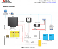
I think I have gone off track with this as the REC BMS diagram shows a shunt near the neg battery post, so svsagres is correct, the BMS has the battery SOC and should be used to control all the chargers. See diagram in Rec Active BMS "User Manual ABMS Victron Wakespeed". So somehow I have to integrate the REC BMS battery signals to control Victron Equipment (such as Smart MPPT, AC Charger and the Orion DC-DC)

The Wakespeed will be controlled integrated using Canbus and the Wakespeed harnass.
That’s the whole point of the Cerbo or raspberry pi plus adapters running venus os. It integrates and ties the whole thing together. It also flies a lot of other stuff, but at its core it’s there to integrate your power system.
 
That’s the whole point of the Cerbo or raspberry pi plus adapters running venus os. It integrates and ties the whole thing together. It also flies a lot of other stuff, but at its core it’s there to integrate your power system.
Yes, now I see that the REC BMS diagram on page 6 of the ABMS-Victron-Wakespeed manual shows a Canbus connection to a CCGX, VenusGX or CerboGX and then other Victron connections to Victron devices. If a CerboGX connected to REC BMS via Canbus is used with "Victron Connect" via bluetooth to connect the other "Smart" Victron Devices, will these devices be controled in accord with the BMS SOC?

I think I will try a new very simple diagram with the bare minimum LFP, and no start battery now, but including CerboGX.
Is it better to run the cables from CerboGX to the MPPT etc, rather than rely on Bluetooth and VictronConnect?

One question I have is if it should be configured as dual bus (charge and loads) or as a single relay since Goboatingnow advises that ABYC wants the battery to be totally disconnected by the BMS.

The CerboGX is about $340, the Color Control GX is about $520 and includes a screen and controls, using the opensource Venus OS which is available on github, with a RPI and a small screen, the cost is considerably less. Goboatingnow is using the RPI/Venus OS approach, which is more flexible but more skilled programming intensive. Summary of the GX range

svsagres essential post #35 about CerboGX and connecting other Victron Equipment.

LATER: In thinking about the "smart" bluetooth devices and what they are capable of doing, is it correct to say that the "smart" bluetooth system using a cell phone app called "Victron Connect" is good for monitoring and setting parameters, but does not provide communications between devices at all?

In an effort to understand the answer to this question, I read VictronConnect - MPPT Solar Charge Controllers and found three statements that were very interesting, which make the statement above incorrect:

Section 2
Battery - Current This reading shows the current flowing-to, or drawn-from the battery terminals of the Solar charger. Note that in the case of the 100/20 Solar chargers and smaller - which have a dedicated load output - a Positive notation alongside the current reading means that current is flowing to the battery; whereas a Negative notation means that current is being drawn from the battery.
Battery - State: ...and it details bulk, absorption (tail current of 1A), float and equalization
End of Section 2
Note that some loads (especially inverters) are best connected directly to the battery. In such cases the load output does not show a reliable reading - the current drawn by the inverter, for example, will not be included. Consider adding a BMV battery monitor which will measure all current going to - or being drawn from the battery, including loads connected directly to the battery …not just the load output terminals of the charge controller.
Last section VE.smart networking
This option is only available when the connection between the charger and VictronConnect is done over Bluetooth. This menu offers the possibility for the user to create or join an existing VE.Smart Network. By doing that, the user allow data to be exchanged between chargers and sensors. Please, refer to the VE.Smart Networking manual for more information about the possibilities over that feature.
So it does appear that data can be exchanged between chargers and sensors via bluetooth and VictronConnect! However this does no necessarily mean that use of a CerboGX can be avoided (Note that in the paragraph above, the REC BMS diagram on page 6 shows a Canbus connection to CerboGX).

Looking at another Victron Connnect App page, I see this statement
Control your devices with ease
Aside from monitoring, you can also operate your device. Easily control the shore power input current limit or switch on your inverter using the VictronConnect app. Together with our VE.Bus Smart dongle, this is an ideal entry level user interface for a complete RV or Marine Victron system.

3.3. VE.Bus Smart dongle limitations
When connected over bluetooth, using the VE.Bus Smart Dongle, only status data, voltages, and other information can be read.
And it can be operated: switch between On, Off and Charger-only mode, and set a Shore current input limit. No changes can be
made to the product.
An MK3-USB is required to change settings and perform firmware updates and settings. And, as that requires a USB port, it is not
possible to change inverter/charger configuration or perform firmware updates on a Apple iPad or iPhone.
VictronConnect does not work with the MK2-USB

So this setup has some limitations.....


Attachments

  • REC-ABMS-Victron-Wakespeed-Overview.png
    REC-ABMS-Victron-Wakespeed-Overview.png
    273.8 KB · Views: 9
Last edited:
Yes, now I see that the REC BMS diagram on page 6 of the ABMS-Victron-Wakespeed manual shows a Canbus connection to a CCGX, VenusGX or CerboGX and then other Victron connections to Victron devices. If a CerboGX connected to REC BMS via Canbus is used with "Victron Connect" via bluetooth to connect the other "Smart" Victron Devices, will these devices be controled in accord with the BMS SOC?

I think I will try a new very simple diagram with the bare minimum LFP, and no start battery now, but including CerboGX.
Is it better to run the cables from CerboGX to the MPPT etc, rather than rely on Bluetooth and VictronConnect?

One question I have is if it should be configured as dual bus (charge and loads) or as a single relay since Goboatingnow advises that ABYC wants the battery to be totally disconnected by the BMS.
The cerbo won’t do Bluetooth to the MPPTs, but I generally don’t trust Bluetooth for mission critical tasks. You’ll need to run ve.direct cables but that’s Perry easy and cheap. Whether you go single bus or dual, the bms will be in full control of both relays. It just gets a little more flexibility in how it does it.
 
The cerbo won’t do Bluetooth to the MPPTs, but I generally don’t trust Bluetooth for mission critical tasks. You’ll need to run ve.direct cables but that’s Perry easy and cheap. Whether you go single bus or dual, the bms will be in full control of both relays. It just gets a little more flexibility in how it does it.
I tend to agree about using bluetooth for mission critical, however note what I found later, at the bottom of my post #112 above.
 
I tend to agree about using bluetooth for mission critical, however note what I found later, at the bottom of my post #112 above.
The issue is getting you bms to control everything. If you’re just doing a simple automotive/vanlife system with some renogy or battleborn “drop ins”,you can get something reasonable especially if you’re running full fractional C, with a smartshunt and the MPPTs communicating over Bluetooth. It’s when you’re getting into more complex systems and/or higher power systems that you need to look at the higher end solutions.

The downside of the colour control GX is that it has a slower processor, not as nice of a screen. This means it can’t run the large image, which includes sognalK and NodeRed. I also don’t believe that it has the tank inputs, digital inputs, or digital outputs.

It all kind of depends on what you want to do with it.
 
From the REC BMS Precharge Manual

High input capacitance systems such as inverters, dc-dc converters, etc. can be exposed to large inrush currents
during the initial power up procedure. If appropriate measures are not employed, these currents can overly stress
or even damage the system components. The pre-charge unit eliminates high inrush currents by charging the input
capacitor before the main contactor switches on, prolonging lifespan of the contactor and other components
dramatically.
The plan is to have no multipass inverter, but we do have a DC-DC charger. Is this component needed?

Also, is it best to attach Wakespeed #12 and #13 (current + /-) to the shunt, even though the REC BMS is also attached there?
Also, should the Wakespeed Battery Temp be connected as well as the BMS Battery Temp?
 
Last edited:
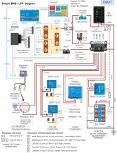
Here is a new DRAFT Diagram for review.
The questions I have are:
1. Is the BMS Precharge needed?
2. What wiring details are missing or incorrect?
3. How should the charge and load disconnects be wired?
4. How should the BMS be setup? Parameters?
5. How should the Wakespeed be setup? Parameters?
6. Should the Wakespeed Battery Temp and Current Shunt be wired? - The BMS is tracking Battery Temp. The current sense should be wired.
7. Is the CerboGX wiring shown OK?
8. How to wire the Orion-Tr DC/DC Charger to CerboGX?

Many thanks to @svsagres @wholybee and @Goboatingnow for all their help to this point.


2. Simple Common Bus BMS Rev 8-15-2022-1.jpg
 
Last edited:
From the REC BMS Precharge Manual


The plan is to have no multipass inverter, but we do have a DC-DC charger. Is this component needed?

Also, is it best to attach Wakespeed #12 and #13 (current + /-) to the shunt, even though the REC BMS is also attached there?
Also, should the Wakespeed Battery Temp be connected as well as the BMS Battery Temp?
So there are two choices for how to configure the current shunt on the wakespeed. The first is as you describe, where it's connected to the battery shunt. This lets the unit do very stable "0 current operation" where once the battery is full, the engine only supplies the house loads. In my case, I have the WS shunt measuring the alternator output directly, but that may not have been the best choice.

I did not bother with the battery temperature for the wakespeed, as it doesn't apply in this kind of situation. It's only needed when doing compensation on Lead Acid batteries. In your configuration, the BMS is telling the alternator what the voltage and current limits are, and the WS500 is doing its best to meet those. It does need the alternator temperature to make sure it doesn't burn out the alternator, but the battery temperature doesn't do anything useful.

Also, the REC battery temperature is a Dallas 1-wire digital temperature sensor, while the Wakespeed expects an analog PTC? sensor, so they can't be shared anyway.
 
Here is a new DRAFT Diagram for review.
The questions I have are:
1. Is the BMS Precharge needed?
Without a MultiPlus, the precharge isn't needed.
2. What wiring details are missing or incorrect?
Just a minor correction, the REC only has one CAN BUS output (though it can be Y'ed I suppose). I'd run your CAN from REC to Wakespeed to the VE.CAN port on the Cerbo. The BMS.CAN is 500kbps, but the Wakespeed integration only works on the VE.CAN port on the cerbo.
3. How should the charge and load disconnects be wired?
With the digital connections (VE.Direct & CAN BUS) there's really not much need for additional control signals, and it can't actually be done with the MPPTs. Instead, you just set their parameters to be conservative if they lose contact with the Cerbo. Most of the time, if your battery isn't too far discharged, this means they'll stop putting out any significant power.
4. How should the BMS be setup? Parameters?
I can feed you my configuration, but it's pretty close to stock, with some of the parameters set based on the battery datasheet.
5. How should the Wakespeed be setup? Parameters?
Similar to above. The wakespeed site has good settings for various cofigurations including what you have here. I just took that, then tweaked it to work nicely with my engine. Because I have a big alternator on a small engine (85A on a 40 year old 1GM10), I have it set to not kick in until the engine hits 1100rpm, and then ramp up slowly before full output at 2800, I also have the feature-in port set to a 50% limit and a minimum 14% field drive so that I can get tach output even when otherwise off (14% produces negligible power on my alternator, just enough to trigger the tach measurement).
6. Should the Wakespeed Battery Temp and Current Shunt be wired?
It's worth having the shunt wired, battery temp not required (as I said in my other post).
7. Is the CerboGX wiring shown OK?
Looks fine, assuming you omitted the VE.Direct cables for the sake of simplicity.
8. How to wire the Orion-Tr DC/DC Charger to CerboGX?
Connect it to one of the relays on the Cerbo. to the jumper on the Orion. I have it wired that way, along with a bit of automation in Node Red to turn the Orion on when the LFP voltage is high enough. The reality is that the Orion just stays on all the time, as when the starter battery is on float, it only consumes a couple of watts, and it is always on float.
Many thanks to @svsagres @wholybee and @Goboatingnow for all their help to this point.


2. View attachment 107065
 
Back
Top