You started this off with some data (we like that) and stated your just starting out/new/learning the 'lingo'
Small steps then: Lets start with the solar panels first.
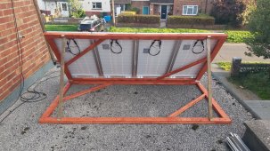
Four 100W solar panels 24.3 VOC and 5.21A (we will assume you mean IMP or the curret at the peak max power point)
The four panels could be connected three different ways:
one string of plus to minus to plus to minus plugged in all the way down the line, this is called series connected and it adds the voltages, but not the amperages. We refer to this as 4S-1P The four PV panels wired this way could output up to 4x 24.3V (97.2Volts) but only 5.21 A total energy of 506 Watts.
two strings of 2 panels in series (like above) but those two strings connected together in parallel (we refer to this as 2S-2P) now your output could be be up to 2x 24.3V (48.6Volts) and now the amperage (current) will be 2x 5.21 = 10.42A and total energy is 48.6x10.42 = 506 Watts.
four parallel strings of one panel each (we call 1S-4P) and now the voltage will be 24.3V and the output amperages add and will be 20.84A total energy output now being 24.3V x 20.84A = 506 Watts - yes, all three arrangements result in different voltages and current but THE SAME total watts - no free lunch.
The important thing to know is you can vary the amperage and voltage by different PV-Panel connection strategies. Lower current/higher voltage means smaller wire sizes needed to safely carry that 506 Watts. But, higher voltages can be a problem for a charge controller if too high. You need to be in a range of both voltage and current that suits the charge controller (lingo: SCC = solar charge controller). I hope this answers your question about series and parallel connections.
Next Step: SCC - solar charge controller - you noted as 30A, 100 Volt.
From the three different PV panel arrangements possible, you could have 24.3, 48.6 or 97.2 volts possible. Generally we often chose the highest that suits the SCC, to reduce wire sizes and line losses. However, 'highest suitable' doesn't mean 97.2V with a SCC that is 100V max. you need some room for a few things (like a solar panel may actually put out higher voltage under cold conditions etc) so in this case 4 panels all in series is too high on voltage. The next step down available to you is 48.6V (2S-2P) so lets look at what amperage this configuration would have: 2S will mean your 5.21A x 2 = 10.42A this is much lower than the max you show of 30A and is therefore safe and could be set up this way.
There remains still one option, the four panels all in parallel. This would output 24.3V and 4x5.21 = 20.82 A still within the limits set by the SCC, but, if the conditions were poor, you might not achieve enough voltage to trigger charging in low light, and the 20.82A will require larger wire, and fuses (than 10.41A) with higher temps & line losses. Being in the UK with periods of low light, I suggest the 2S-2P connection as likely your best option. And to answer your question earlier - YES a fuse between the PV and the SCC is a good safety measure since it is entirely possible that some day, something happens to those lines or the insulation on them, and you need a fuse to cut off the circuit safely. But what size fuse? at 10.41A go with a 15A fuse, this will prevent tripping under normal conditions but be available if the current exceeds 'normal' current very much. Renogy (and others) make an inline fuse with MC-4 connection ends that can go right into your connections to the panels. They also make a 1x2 splitter to get the parallel to series connections you need if you go with 2S-2P configuration.
Next Step: Wire sizes PV to SCC
You comment that the PV wires look 'too small' however you can be sure they are sized to suit the panels there are on. If we continue with the 2S-2P arrangement we see that you need to safely carry 10.41 Amps, and if we allow some overage, 1.25x10.41 = 13Amps. {using a suitable calculator - I used the DC Cable sizing tool on Solar-Wind Co UK} picking some normal parameters, 3% line loss, 6 m run length 13A 48.6 volts it spits out 2.5mm2 cable (14ga. AWG on our side of the pond) you can be sure the PV panels come with larger than this size, and in the data sheet it will tell you the max parameters for the strings which this size cable will support. Since the calculator reports a smaller wire size, I would just match the PV cable size (likely 10AWG/6mm2) for your extension leads. This will just mean low line losses, and is not adding to your expenses in these sizes. Be sure to use UV rated cables where exposed to direct sunlight. I am not familiar with UK rules or cable designations, in many areas the cables need to be protected from rodents/birds that might chew/peck on the wire insulation, you should check local requirements.
Next Step: SCC to Battery
Your Renogy MPPT will convert the PV DC voltage and amperage to a suitable Voltage and Amperage to charge the battery(ies). The cables will now be carrying the same energy (watts) as the PV panels sent out, but now at a voltage closer to the battery voltage. In fact the MPPT will vary the voltage, but lets not get too complacated. Lets "say" the '12 volt' battery charges at 14VDC. Your 506 Watts will then be: 506/14V = 36Amps (yes there will be some losses, and all that but lets stay on track here). To carry the 36Amps you again use the DC calculator: I don't know the proper cable length so took as an example "2-meters" and plugging in the other values, it spits out 10mm2 cable (8AWG) -this is one place where if you had picked 24VDC for the batteries you would see a much smaller cable size {4mm2, 12AWG} - also this cable will be Very Sensitive to cable length, longer cable much bigger cables reqired. A 2-pole disconnect is a good idea here, for maintenance and safety reasons, oh and "disconnect" is a fancy word for "switch" and in DC it needs to be a DC rated 'switch'.
Next Step: Battery to Inverter
You noted your inverter is the Renogy 2000 and I am not familar with this model but assume it outputs 2000 Watts (perhaps with some peak output up to x 2 of this value?) and since your in the UK your inverter is outputting 230VAC power. So now the battery will supply DC voltage to the inverter, and we need the cable size to be large enough to safely supply the amperage the inverter could/may draw. The inverter may have instructions with it that specify the minimum wire size, if so follow that. By calculation, if we use 2x 2000 W as a peak draw, 4000W/12VDC = 333Amps (a lot of amperage, in fact too much) you noted a 200A fuse between battery and inverter, this will protect the wire up to 200A. Lets use 200A x 1.25 for the wire size, to allow your 200A fuse to protect this wire size: from the DC wire size calculator and again assuming 2-meters max cable length, it spits out 70mm2 (2/0-AWG) Although I typically go one size larger, if this will fit the inverter, to reduce line losses/remain cooler etc. Again longer cable will have huge impact on the DC wire sizing. Be sure to work carefully around battery terminals, a slip with a 'spanner' can lead to a bad day.
House wire/plugs? I don't know if the Renogy 2000 comes with outlets right on the inverter or if it needs to be wired into some usable recepticales - I suspect in this size, these units have outlets right on them.
Hope this helps you out, maybe it just created new questions, if so just ask, someone will step up and reply.


 .
.