diy solar

diy solar

Small Garage Set Up.

LDVV

New Member
Joined
Feb 26, 2022
Messages
169
I'm having trouble trying to figure out how literally I should take the specs for this MPPT (given all the talk of overpanelling etc).

This is what I have:


I plan on connecting two 12v 100ah batteries as BATT1, then repeat for BATT2. I'd like to use the batteries in parallel, keeping it at 12v.

The MPPT instructions read:

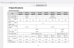
*Max. PV Input : 390W/12V

*Max. PV open circuit voltage: 100V

My spare panels range from 265w to 315w. As the "max input is 390w", can I somehow use two (or more?) panels, and get around the limits via wiring the panels in a certain way.
 
390w at 12v means it will use up to 390watt. Your panels can be 500w or whatever you desire. I would put a couple of the 315w panels on it if I wanted to let it charge at full amps. Read the manual and make sure you mount it properly, so it can get good air flow.

1658346244324.png
 
I'm having trouble trying to figure out how literally I should take the specs for this MPPT (given all the talk of overpanelling etc).

This is what I have:


I plan on connecting two 12v 100ah batteries as BATT1, then repeat for BATT2. I'd like to use the batteries in parallel, keeping it at 12v.

The MPPT instructions read:

*Max. PV Input : 390W/12V

*Max. PV open circuit voltage: 100V

My spare panels range from 265w to 315w. As the "max input is 390w", can I somehow use two (or more?) panels, and get around the limits via wiring the panels in a certain way.
Which model number do you have? Note one with 60v PV input and one with 100v PV input. You will need the 100v if you want to put two large panels in series. I guess you could run them parallel with either unit if your voltages matched up.
 
Which model number do you have? Note one with 60v PV input and one with 100v PV input. You will need the 100v if you want to put two large panels in series. I guess you could run them parallel with either unit if your voltages matched up.
Thanks for the replies.

I will have a proper read soon (busy getting the Kids ready!).

I have the 100v version. The max. output of any of my panels is 40v.

Given my battery proposal, am I better in parallel, or series?
 
Last edited:
Thanks for the replies.

I will have a proper read soon (busy getting the Kids ready!).

I have the 100v version. My max. panel output is 40v.

Given my battery proposal, am I better in parallel, or series?
Parallel will take twice the wire size, so if it is a long wire run to the panels, consider that. I would do series (myself). I have a 40amp EPEver AN with 2s2p 300w panels on a 24v battery. I get about 75-80v input with 60cell panels.
 
Parallel will take twice the wire size, so if it is a long wire run to the panels, consider that. I would do series (myself). I have a 40amp EPEver AN with 2s2p 300w panels on a 24v battery. I get about 75-80v input with 60cell panels.
I did consider 24v for that reason (wire gauge), but I'd really like to run some stuff straight off the batteries. Lights etc.

I could always use a *24v to 12v* device, but am I adding another step of potential failure, or load/drain?

If I did wire the batteries as 24v, increasing useable limits of the Charge Controller, could I also be within safe limits using 2s2p?
You can use a higher voltage on the solar panels and doesn't have to match the battery voltage. If you have a 12 volt system you need at least 15ish volts on the solar panel side. You could do 60+ volts depending on the panels & charger to save cost on the wire size from solar panel to MPPT charger. The voltage panel voltage & watt limit will be determined by the charger.

From here it's just a math game. once you know the amp usage you can determine the wire size

Series - 12v 200 watt + 12v 200 watt = 24 volt 400 watts @ 17 amps
Series - 12v 200 watt + 12v 200 watt + 12v 200 watt + 12v 200 watt = 48 volt 800 watts @ 17 amps

Parallel - 12v 200 watt + 12v 200 watt = 12 volt 400 watts @ 33 amps
Parallel - 12v 200 watt + 12v 200 watt + 12v 200 watt + 12v 200 watt = 12 volt 800 watts @ 67 amps

Amps = Watts / Volts
 
I did consider 24v for that reason (wire gauge), but I'd really like to run some stuff straight off the batteries. Lights etc.

I could always use a *24v to 12v* device, but am I adding another step of potential failure, or load/drain?

If I did wire the batteries as 24v, increasing useable limits of the Charge Controller, could I also be within safe limits using 2s2p?
I was not suggesting you do 24v battery. Just stating what my setup was....running 2series on a 100v max PV input Tracer AN.

What are the spec on those large panels?
 
I was not suggesting you do 24v battery. Just stating what my setup was....running 2series on a 100v max PV input Tracer AN.

What are the spec on those large panels?
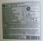
My two larger spares...

IMG_20220722_073409.jpgIMG_20220722_073356.jpg
 
So if you put two in series your wire size would need to be able to carry only 10 amps, but on parallel two panels would be close to 20 amps. The 10 amps will create less heat where you connect things, which is a good thing. Some MC4s are rated up around 30 amps but they are a point of possible failure when they have been used a bit and are not as tight as when new. So 50% of the amps would result in 25% of the heating on any less than ideal connection. I would vote for series connections for those reasons. Smaller wire and less terminal stress.
 
So if you put two in series your wire size would need to be able to carry only 10 amps, but on parallel two panels would be close to 20 amps. The 10 amps will create less heat where you connect things, which is a good thing. Some MC4s are rated up around 30 amps but they are a point of possible failure when they have been used a bit and are not as tight as when new. So 50% of the amps would result in 25% of the heating on any less than ideal connection. I would vote for series connections for those reasons. Smaller wire and less terminal stress.
Understood, thanks.

Also, to confirm; two of the shown REC panels, in Series, is my input limit for this Charge Controller?
 
Understood, thanks.

Also, to confirm; two of the shown REC panels, in Series, is my input limit for this Charge Controller?
2 in series should give you about 80v, which is under the 100v. But when it gets cold, that 40Voc will be higher and higher the colder it gets. Limit? Below the max but limited to 2s and you can't do 3s, if that is what you are asking.
 
2 in series should give you about 80v, which is under the 100v. But when it gets cold, that 40Voc will be higher and higher the colder it gets. Limit? Below the max but limited to 2s and you can't do 3s, if that is what you are asking.
Yes, I was being ambitious as I don't fully grasp the "over panelling" yet.

The manual reads that, at 12v, there is a 390w input limit. Despite that, a few have told me that two panels would be fine, and that's not far off double the stated limit.
 
Connect your batteries in parallel to BATT1 terminals for a 12v system. Batt2 output is used in RVs to provide a low 1 amp maintaining charge to the starter battery. Batteries connected to batt2 will not be charged, only maintained.
In other variants of the charger its stated that around twice the rated panel power is acceptable whenever panelling. Although 2 of your panels in series will exceed the 390 watts, the controller output will be limited to 30 amps.

Its not too clear why you have a dual output charger for a garage set up.

Mike
 
Last edited:
Yes, I was being ambitious as I don't fully grasp the "over panelling" yet.

The manual reads that, at 12v, there is a 390w input limit. Despite that, a few have told me that two panels would be fine, and that's not far off double the stated limit.

The term "over panel" is a bit of a loose term. In the days of PWM chargers (still valid solution) if the battery really needed charged, the charger would allow the battery to load the solar array with what looked like a short. The panels are made to output in a shorted condition but the charge controller passing all of those amps could only take so much current so it was not wise to put in an array that was able deliver enough current to overheat the controller. Keep in mind that with the PWM, the battery is the load.

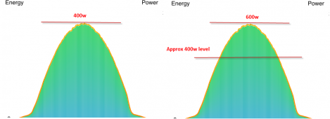
With MPPT, the internals of the MPPT create a load to charge some capacitors that in turn drive the current to the battery at the voltage that the battery needs for proper charging. So the load is dynamically controlled by a microcomputer which also gives it the ability to tune the load to match the best power that the panel can deliver at the current solar conditions. Because of its design, MPPT is current limited and if you put more panels on one, it will only use what its programming will allow. Below is an image of what solar production looks like in a normal sunny day, if you demand 100% of what the array can deliver. Never mind the little drop on the right end of the curve, that is shade from trees. The curve is not to scale with the noted watts but just an example. If you have 400w of panels, you will get 400w for a few minutes on a few days of the year when the fixed array panel is facing right at the sun, the time of day is just right, and the weather is not too hot. So you will really never produce your 400 watts. So you put in slightly larger or maybe more than slightly larger panel watts so you can make 400w at least some measurable part of the day. In the right side of the image, it depicts how a 400w line might land on a 600w panel array. If your charger was limited to 400w, you could get 400w for maybe 3 to 5 hours rather than 15 to 30 minutes...on a good day.


1658488770080.png
 
DThames, thanks for the very elaborate response. More understood now.

I'd also read that, for a plan this small, I wouldn't need an Earth. I don't like the sound of that. Shouldn't I have a spike in the ground somewhere? At least for the Panels? Also, the Charge Controller needs to be Earthed. Can I do this direct to the Batteries?
 

Attachments

  • IMG_20220731_150737.jpg
    IMG_20220731_150737.jpg
    331.2 KB · Views: 3
DThames, thanks for the very elaborate response. More understood now.

I'd also read that, for a plan this small, I wouldn't need an Earth. I don't like the sound of that. Shouldn't I have a spike in the ground somewhere? At least for the Panels? Also, the Charge Controller needs to be Earthed. Can I do this direct to the Batteries?
In the event that the metal frame of a piece of electrical equipment becomes electrically "hot", having that frame grounded will connect that frame to earth ground. Most shock hazards are from a person touching something that is ground (like the ground) and then touching something that is electrically energized, causing a current to pass through their body. If you connect your solar panel frames to earth, a person can't create a current path through their body from the panel frame to ground because those two points are (with a good ground wire/rod) the same voltage. A charge controller's metal frame/case should be connected to ground for the same reasons. Batteries are not a place to connect a ground. On most US cars, the frame is used to carry the negative side of the battery to most loads in the car, so that you only need a positive wire and the chassis/frame "ground" to complete the circuit. This use of the term "ground" is not the same as "earth ground", which is often translated very well as "earthed".
 
In the event that the metal frame of a piece of electrical equipment becomes electrically "hot", having that frame grounded will connect that frame to earth ground. Most shock hazards are from a person touching something that is ground (like the ground) and then touching something that is electrically energized, causing a current to pass through their body. If you connect your solar panel frames to earth, a person can't create a current path through their body from the panel frame to ground because those two points are (with a good ground wire/rod) the same voltage. A charge controller's metal frame/case should be connected to ground for the same reasons. Batteries are not a place to connect a ground. On most US cars, the frame is used to carry the negative side of the battery to most loads in the car, so that you only need a positive wire and the chassis/frame "ground" to complete the circuit. This use of the term "ground" is not the same as "earth ground", which is often translated very well as "earthed".
Thanks again for the explanations.

In this particular case with it being marketed/designed for a vehicle, the earthing point would be the chassis - which in turn, returns to the battery.

Obviously I wouldn't want any lightning strike to enter the house/batteries, so I wouldn't earth panels -> battery.

However, I wasn't sure if the frame of the actual charge controller, in this case, was an exception.
My EPEver AN series have a ground post/screw on them, close to the holes where you bolt down the unit, as I recall.

(I was not thinking about an RV install)
 
Back
Top