diy solar

diy solar

So... Set me straight on a few things related to battery C ratings and BMS capacity... Please!

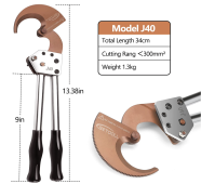
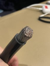
Hint; use Scotch bright just to put a shine on the inside of the lugs. Just a few turns and blow out the dust just before you crimp. Use No-Ox-ID “A” special on electrical contacts but avoid the threads. Don’t use anything on the tinned cable strands, just clean fresh metal to metal. Everything I found on Amazon. Do not get the little ratcheting cable cutters, those work fine for the thicker strand cables like you find in utility wiring. Fine strands will cut amazingly easy with the long handle kind as seen in the picture. It’s actually fun. To cut the vinyl insulation, I used a modified tube cutter where the wheel was made to a knife edge. You may be better off asking around here for an alternative wire stripper unless you have access to a machine shop. If you are just cutting a few ends you can just use a sharp box cutter. With care you won’t nick strands or fingers. I use flat smooth bottom nuts with no serrations. If you have room left on the stud you can use a Bellevue washer too. I like these little eye terminals (Spoby) because mine were actually brass not copper as listed, they don’t distort with the washer pressure. I remove the red heat shrink to crimp. I use clear 1/8” adhesive lined and insert info inside. I found that only the small slot on my MC4 crimper with jaw turned close to the hinge could tightly crimp a doubled(folded) balance lead. If you are making short jumpers you must bend them slightly to a slightly smaller arc than what you need because the cable will spring out and rotate slightly (see how I over lapped the buss bar?) If you want finished lug hole spacing at 5.650”,you crimp at 5.550 to allow for relax distance. I used a 16 ton crimper and modified the “70”size die (for 2/0) and “120” (for 4/0) in the areas marked with an X. Remove a little at a time till your test crimp/W cable has a crisp cornered hex but little to no flash/extrusion. It can be done VERY carefully with a grinder but sneak up on it evenly. I did one that way in the middle of nowhere, the other I cheated with a milling machine. Good luck. 55D0DBC0-8D94-42F8-9FAA-3530EFFDAB1F.jpegC66CD08C-C209-431B-B538-3A4341E0DBD9.jpeg655C80A9-F8D2-4F36-BF58-886E21079DDB.jpeg7E269735-3C32-4F20-A948-EF51B0325A78.jpeg7D1F1E2E-C7D7-4501-8CA8-F1CC16DED678.jpeg
 
Last edited:
What is the handle length of your Flytuo cutters? 18" 24" They are out of stock on Amazon, so looking for an alt. source. Thanks!
 
What is the handle length of your Flytuo cutters? 18" 24" They are out of stock on Amazon, so looking for an alt. source. Thanks!
Dang it! Yeah, these are the 24’s. Over a hundred cuts and mine are still sharp as a razor. Got no other the recommendation. Just don’t cut steel cable or wire rope with any of this type. All you can do is look at the reviews and ignore the clowns that didn’t pay attention to what it’s for.
 
I ended up buying these (before I had your recommendation). I've used it a few times now and the cuts are clean and straight. I will see if this remains true over time... Thanks for all of the advice! This is great information!
 

Attachments

  • Screenshot 2022-12-03 at 17.23.59.png
    Screenshot 2022-12-03 at 17.23.59.png
    627.6 KB · Views: 6
Last edited:
I ended up buying these (before I had your recommendation). I've used it a few times now and the cuts are clean and straight. I will see if this remains true over time... Thanks for all of the advice! This great information!
That’s good to know, glad you got some that work. I bought one of these little ones and had it too long to return it. I cuts the corse strand stuff like 3/0 THHN alright but using it on fine strand welding or marine cable it bypasses = sucks. I even tighten the pivot point and sharpened it but no joy. It’s also very slow compared to the loppers. 944E589F-DBFC-4F29-9F38-BFE35AB47A08.jpegD23EB0EE-0EA1-4668-9CBF-C9C21BE35A99.jpeg
 
Last edited:
Trying to figure out how to organize (2x12) two rows of 12 for 24 total cells to provide 24 volts.

I'm thinking that I can do 3P8S but don't know how to arrange them so that the bus bars are more of less of equal length.

I'm working with some constraints. You can see from the picture that access to my battery box is inconvenient. Currently the batteries are raised and lowered into the ship's battery box using a pulley system. (not shown here) The opening shown in this picture is one of three openings and is the largest.

Getting the batteries in and out is a bit of a pain. My thoughts are to create four 24 volt battery packs of 2 rows of 12 cells, by buying/building a metal box with lifting points that I will lower into the battery box and wire each battery box pack in parallel to the main bus. Any thoughts will be greatly appreciated!
 

Attachments

  • Screenshot 2022-12-04 at 23.51.03.png
    Screenshot 2022-12-04 at 23.51.03.png
    1.5 MB · Views: 7
  • Screenshot 2022-12-04 at 23.49.32.png
    Screenshot 2022-12-04 at 23.49.32.png
    230.6 KB · Views: 7
  • Screenshot 2022-12-04 at 23.13.53.png
    Screenshot 2022-12-04 at 23.13.53.png
    234.7 KB · Views: 7
Last edited:
I found this on a Google Docs site. Seems correct for 3P8S.
 

Attachments

  • Screenshot 2022-12-06 at 01.15.37.png
    Screenshot 2022-12-06 at 01.15.37.png
    238.5 KB · Views: 6
I checked my configuration by re-drawing the battery connections this way. To my eye, it properly shows a 3p8s configuration. Does anyone know where to get heavy duty tinned-buss bars that can carry 300+ amps? Going with the Fortune 100ah batteries that are rated for 2C continuous gives me a battery that will provide 600 amps at 24 volts with this configuration. I'm still very much a newbie at this. If anyone sees any issues with my logic please let me know!
 

Attachments

  • Screenshot 2022-12-08 at 01.17.08.png
    Screenshot 2022-12-08 at 01.17.08.png
    145.7 KB · Views: 3
8S 12P battery configuration
12P x 200A(2C) = 2400A (continuous)

Note: busbars are only rated for 150A so 12P x150 = 1800A (continuous)

I agree with using a contactor BMS
Be sure to configure your continuous current on the BMS to 15% above what you need.
JK makes a 1000A contactor BMS but not sure how it will do in a marine environment.
Do you have a source or link to the JK 1000A contractor?
 
Do you have a source or link to the JK 1000A contractor?
I just ordered these contactors and BMS for the first time yesterday so I cannot say if they are any good but the other JK BMSs I bought have been great so far. Since they are split port, you will need 2 contactors for discharge and another one for charge.
You can use other contactors with this BMS but these don't use too much power on the actuator coil, which must be actuated when the BMS is charging/discharging.

It appears you can use two (or more) of the 500 amp contactors together in parallel for continuous current above 1000A...


I think this 5A active balance model may be priced wrong. It is usually higher priced than the 2A balance 100A model (like below).


Here at Hankzor it is cheaper

I would like to hear from anyone who has experience with this BMS
 
Last edited:
I checked my configuration by re-drawing the battery connections this way. To my eye, it properly shows a 3p8s configuration. Does anyone know where to get heavy duty tinned-buss bars that can carry 300+ amps? Going with the Fortune 100ah batteries that are rated for 2C continuous gives me a battery that will provide 600 amps at 24 volts with this configuration. I'm still very much a newbie at this. If anyone sees any issues with my logic please let me know!
I have build many batteries successfully (up to 8p) using this buss bar configuration.

While this is the simplest (probably most reliable) and most economical configuration, many people would split the batteries onto three separate BMSs for redundancy and use smaller buss bars/wiring.

I assume you are interested in the Fortune batteries due to space/weight limitations?
For close to the same price, you could do a 3p8s configuration with 280/302Ah EVE batteries that could do 750+ amps continuous and you would get three times the capacity and rated for more cycles.
I will take another look at the 280/302Ah EVE batteries. Do you have a link to a reliable source of grade A EVE batteries and the specs? I've watched a number of YouTube videos that are saying that they received Grade B EVE batteries instead of the A grade versions they ordered.

I'm still doing my research, and Will Prowse speaks highly of the Fortune 100ah cells. I like the plastic end caps and the ability to use thread rods to secure the batteries. Also, they are rated at 2C continuous and 6C for 10 seconds.

I need to run a bow thruster off of this house bank. It draws 650 amp continuous. It is used in 3-10 second bursts. So the need to be able to carry large current. And I need to plan for the inrush current. (I've looked real hard at separating the bow thruster from the house bank, but space limitations make that nearly impossible using AGM batteries mixed with LiFePo4 for the house side.)

This link has both storage grade and certified automotive grade
It also has the datasheets. The LF280K is rated for 6000 cycles at 80%DOD


Attachments

  • LF280K Specs.png
    LF280K Specs.png
    423.3 KB · Views: 2
This link has both storage grade and certified automotive grade
It also has the datasheets. The LF280K is rated for 6000 cycles at 80%DOD

If you are say going with sixteen cells but your only putting eight in each box, the jumper between the box can’t have less resistance than any of the busses you have used between the cells. You may have to run a 4/0 at 12” to do this. An inexpensive internal resistance meter can tell you. A typical nickel plated copper buss bars will read .07 on the display and a jumper with .09 to .04 is plenty close enough. I have checked to see if the meter readings actually correlate to voltage drop with a 100 amp load and they do exactly. I don’t understand it, but tinned cable has half the voltage drop. It’s probably because of tinned wire on tinned lug. The actual cable loss is probably the same. So it’s Ancor cable and Selterm lugs from now on (both are actually UL!l
Dang it! Yeah, these are the 24’s. Over a hundred cuts and mine are still sharp as a razor. Got no other the recommendation. Just don’t cut steel cable or wire rope with any of this type. All you can do is look at the reviews and ignore the clowns that didn’t pay attention to what it’s for.
Any recommendations for standardizing on a single type of connector? I found this on Amazon. Because I am on a boat, I want to find a connector type that supports 22-10 gauge, is reasonably weather tight, smallish in size and can used in a variety of electrical projects and electrical upgrades around the boat and for my LiFePo4 build. I found this Flytuo kit on Amazon.
 

Attachments

  • Screenshot 2022-12-13 at 06.55.05.png
    Screenshot 2022-12-13 at 06.55.05.png
    1.2 MB · Views: 4

A few comments on contactors. This contactor is rated for 500A at 85 deg.C with 400 mcm conductors. I'm not sure how hot the contact get. Is the contactor (for this specification) in an ambient cooled environment to keep contact temperature from rising above 85C?

The spec has <100 mV contact voltage drop at 200A. That means the contact resistance is about 0.1V / 200A = 0.5 mohm. At 500A the power dissipation at the contacts is: P = I^2 * R = 125W. The contacts will get extremely hot when conducting 500A. The spec is also relying on the big cables conducting heat out of the contactor.

The motor probably has some inductance. Inductance is usually the cause of early contactor destruction. The greater the inductance, the greater the voltage which is generated as the contacts open, resulting in higher energy sparks. The contacts will get pitted (from sparks burning them). The more the contacts become pitted, the greater contact resistance gets. I don't think several contactors in parallel will help. They will not open at exactly the same time. The last one to open will get all the damage.

Look and see how much inductance the motor has. You can add a diode and capacitor/resistor) across the contacts to avoid the spark. I've done that many years ago to a relay that energizes a solenoid that operates a vehicle mounted military machine gun. The relay wasn't rated for the solenoid inductance. When the marines operated the gun in single shot mode, with fast sequence of shots, the contacts get so hot that they fuse together. All of a sudden the gun is out of control.
 
Last edited:
Any recommendations for standardizing on a single type of connector? I found this on Amazon. Because I am on a boat, I want to find a connector type that supports 22-10 gauge, is reasonably weather tight, smallish in size and can used in a variety of electrical projects and electrical upgrades around the boat and for my LiFePo4 build. I found this Flytuo kit on Amazon.
Those small connectors are only for small stuff perhaps balance leads and some kinds of bms’s are sensitive to lead length, the JK is not. As for connections between boxes as continuation of a series, you must use a bolted connection of either a extra heavy buss or lugged cable to make up for the distance. No plugs! Off the top of my head, to equate the resistance of the usually supplied plated buss bars to a 1 foot cable, you’d probably need to go 4/0 size. You will have to provide safe, sealed for a passage between the boxes. Consider the approximate weight of 8 280/310
class cells and box to be about 100 pounds if I remember correctly.
 
Last edited:
8S 12P battery configuration
12P x 200A(2C) = 2400A (continuous)

Note: busbars are only rated for 150A so 12P x150 = 1800A (continuous)

I agree with using a contactor BMS
Be sure to configure your continuous current on the BMS to 15% above what you need.
JK makes a 1000A contactor BMS but not sure how it will do in a marine environment.
If I double up the bus bars (use two between each terminal) will that provide 300A of current carrying capability? I'm also pricing tinned copper flat stock to use instead of the supplied bus bars.
 
If I double up the bus bars (use two between each terminal) will that provide 300A of current carrying capability? I'm also pricing tinned copper flat stock to use instead of the supplied bus bars.
A few comments on contactors. This contactor is rated for 500A at 85 deg.C with 400 mcm conductors. I'm not sure how hot the contact get. Is the contactor (for this specification) in an ambient cooled environment to keep contact temperature from rising above 85C?

The spec has <100 mV contact voltage drop at 200A. That means the contact resistance is about 0.1V / 200A = 0.5 mohm. At 500A the power dissipation at the contacts is: P = I^2 * R = 125W. The contacts will get extremely hot when conducting 500A. The spec is also relying on the big cables conducting heat out of the contactor.

The motor probably has some inductance. Inductance is usually the cause of early contactor destruction. The greater the inductance, the greater the voltage which is generated as the contacts open, resulting in higher energy sparks. The contacts will get pitted (from sparks burning them). The more the contacts become pitted, the greater contact resistance gets. I don't think several contactors in parallel will help. They will not open at exactly the same time. The last one to open will get all the damage.

Look and see how much inductance the motor has. You can add a diode and capacitor/resistor) across the contacts to avoid the spark. I've done that many years ago to a relay that energizes a solenoid that operates a vehicle mounted military machine gun. The relay wasn't rated for the solenoid inductance. When the marines operated the gun in single shot mode, with fast sequence of shots, the contacts get so hot that they fuse together. All of a sudden the gun is out of control.
Keep in mind that the BMS contactors should only open under load in the case of emergency battery protection. Other protective over charging and discharging measures should prevent the contactors from changing states under load ever.
 
If I double up the bus bars (use two between each terminal) will that provide 300A of current carrying capability? I'm also pricing tinned copper flat stock to use instead of the supplied bus bars.
If you are configuring the batteries in parallel like above, the full 300 amps will only be present on the bus bars between the parallel groups of cells and at the ends.
 
Back
Top