diy solar

diy solar

Sol-Ark 15K All in One Inverter Released.

So in effect, would this make my main panel of sub panel of the first disconnect? I have 3 additional sub panels in the house, would that make them sub-sub panels? Is that allowed?

The diagrams in the solark manual indicate a ground/neutral bond still at the main panel which is what makes me think that just grounding the first disconnect might be appropriate in this case. This does seem to conflict to the ground/neutral bond rule at the first panel like you are saying though. Maybe a call to solark will get it figured out.

My Service Entrance Rated ATS comes with ground and neutral bonded.
 
I see, I misread your post. That does seem to make sense the way you sketched it out. It looks like adding a transfer switch complicates the hell out of it since you'll have the grid input/output AND the load output to contend with. I agree that just having a 200A breaker on the main panel should eliminate the problem.

But the transfer switch allows you to disconnect SolArk and remove it for service.
(Still have to shut off power while disconnecting wires from SolArk, but just a simple throw of the switch for family member to restore power prior to that taking place.)

I get a similar function with 200A main breaker in panel interlocked to 100A "Generator" breaker, which is fed by my battery inverter PV system. No separate transfer switch needed, but one of the two feeds is limited by maximum 125A branch circuit breaker that could be installed.
 
Sol-Ark’s email response:

”The diagram does not show a separate fused disconnect. However, depending on the AHJ or code in your area, a fused disconnect
is still necessary and the ATS does not work as a substitute.”

Not sure if they addressed the specific ATS I have (I did send them that model info)

My ATS is Service Entrance Rated with Utility Service Circuit Breaker

If your ATS has an appropriate circuit breaker on grid input, e.g. 200A and at least 22k AIC, that protects ATS and downstream 200A breaker panel.

In the case of SolArk also connected to grid before ATS, the 200A breaker protects panel from seeing 200A + 62.5A = 262.5A.
But in that case, it doesn't provide protection for SolArk input, which also needs 200A OCP. Another 200A breaker or fuse, and disconnect, is needed for SolArk.
 
But the transfer switch allows you to disconnect SolArk and remove it for service.
(Still have to shut off power while disconnecting wires from SolArk, but just a simple throw of the switch for family member to restore power prior to that taking place.)
You have to shut power off to remove Sol-Ark, why not just connect the wires to the main panel at that time (could even have a bus bar setup for that)? I see no need for a transfer switch. If the Sol-Ark fails, you will still have service as the grid will pass through.
 
If the Sol-Ark fails, you will still have service as the grid will pass through.
However if you have to remove the SolArk for service there will be no pass through. An interlock could serve that purpose or a temporary jumper until the SolArk is replaced. It is simply a matter of user preference and convenience.
 
You have to shut power off to remove Sol-Ark, why not just connect the wires to the main panel at that time (could even have a bus bar setup for that)? I see no need for a transfer switch. If the Sol-Ark fails, you will still have service as the grid will pass through.

True. If it continues to pass through while inverter is dead (unlike my Sunny Island), family member doesn't need to do anything prior to electrician's visit.
Electrician turns off power briefly while removing Sol-Ark and rerouting grid directly to main panel.

If feed to/from SolArk goes through a conduit "T" with matched lengths, this may be doable by pulling and stuffing wire to new location. Although, doing anything with 2/0 is a bear. Additional wires already routed, with unused ends capped, would eliminate need to re-route. Or a box to put in place of SolArk with Polaris connectors for loop back.

Good to work out the details prior to initial installation, know how power to property should work during repair.
Then leave a note inside the wiring box for electrician "Please re-wire grid straight to main panel when removing SolArk" or whatever is needed.
So things happen correctly while you're away, or after you're gone.

In my case, separate breakers feeding inverters (can't take 200A) and $100 worth of interlock and backfed breaker takes care of isolation. Just needs clear documentation for family members.
 
However if you have to remove the SolArk for service there will be no pass through. An interlock could serve that purpose or a temporary jumper until the SolArk is replaced. It is simply a matter of user preference and convenience.

Yep. That is why I was correcting the notion that the family would be without power until they throw the transfer switch.

I will just move the wires over to main panel, or another means as I suggested is have a bus bar (Polaris connectors, etc) shared to the main panel. No need for a transfer switch as live wires going to the Sol-Ark will have to be dealt with.
 
So you gotta whip out the manual and menu before throwing a switch? What if it is an automatic transfer switch??
This ought to be an electrical signal to SolArk. "Other" brands do that.
SolArk takes care of it by having a separate "generator" input, but if you put PV there and generator on switched main input, need to prevent backfeed.

Seems like you ignored my response to your question (of my post). My response immediately precedes the post to which you are replying. It gives possible explanations for all of the above questions/concerns/postulations.
 
Sol-Ark’s email response:

”The diagram does not show a separate fused disconnect. However, depending on the AHJ or code in your area, a fused disconnect
is still necessary and the ATS does not work as a substitute.”

Not sure if they addressed the specific ATS I have (I did send them that model info)

My ATS is Service Entrance Rated with Utility Service Circuit Breaker

I asked for clarification. Sol-Ark responded that the 15k doesn’t need or require a fused disconnect. I think, poorly worded response, but…

If it is needed, it is by code or AHJ.

From Sol-Ark:

”If the features for your ATS complies with the code or AHJ in your area, then it will work. However, from the inverter, it is not needed or needed.
The question on whether your ATS's circuit breaker constitutes as a fused disconnect would ultimately be up to the utility or AHJ. In some cases, if
it does meet their requirements, they may require a separate fused disconnect that is standalone. Again, this is up to your AHJ or utility in your area.”

Assuming this latter response from Sol-Ark is accurately quoted (I assume you just did a cut & paste from their email response), it seems to be another poorly worded response from them. First: "... it is not needed or needed...". I would assume they meant "required or needed"? Second: "...if it does meet their requirements, they may require a separate fused disconnect...". I would assume they meant "...if it does not meet their requirements..."?
 
Assuming this latter response from Sol-Ark is accurately quoted (I assume you just did a cut & paste from their email response), it seems to be another poorly worded response from them. First: "... it is not needed or needed...". I would assume they meant "required or needed"? Second: "...if it does meet their requirements, they may require a separate fused disconnect...". I would assume they meant "...if it does not meet their requirements..."?

Yep, that was a cut and paste.
 
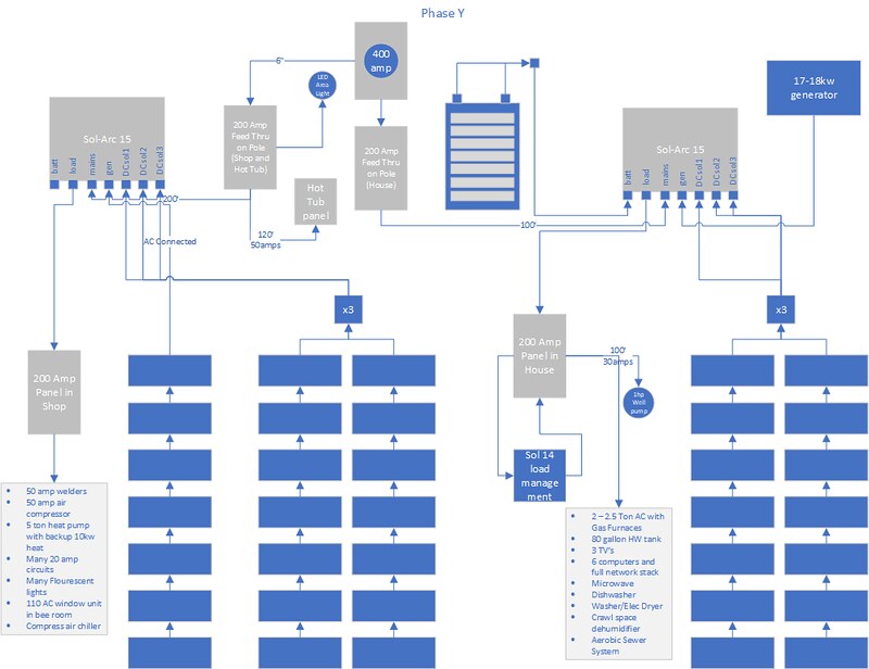
I'm in the early planning stages of building a system. I like the abilities of the sol-ark 15 and think it will fit what my needs/goals are. I will have to do this in a phased approach since money doesn't grow on trees, but the basic layout of my place is 400 amp service comes in to 2 200 amp feed thru lug panels on my pole. One panel current supplies the house and has a 30 amp breaker for my water well on it. The other panel has a 50 amp breaker for my hot tub, breakers for my patio as well and feeds on to my 40x80 shop. Everything is trenched underground from the pole. The breaker box in the house is inside built into the wall, power is fed up in conduit from the crawl space.

My first phase will be to add a generator as we can and have had week long periods of no electric in the winter, I've gotten us by with our fire place, a 5kw generator and a 10kw welder generator on a trailer but I only run them periodically not long term, I store 50 or so gallons of gas for winter time use. I'm not new to wiring, I've done most of it here on my place or had the help of my brother at one point or another for advice or bouncing sizing requirements off of, including the full shop wiring. Currently building conduit runs of rigid outside and emt inside for my 5 ton heat pump going into the spray foamed shop.

I'm kind of stuck on the first step, do I just start with an ATS and then add the 15 later and get a 20 to 24 kw propane generator? Or do I go 17/18kw generator and 15. I can manage loads to keep the 17/18kw useable but plan on adding the sol 14 at some point in the house wiring to manage the loads. The well will either need to get it's own power plant to run it offline, a plug for the generator or I will trench a new line to the house panel and handle it with the sol14 as well. Still up in the air about it. I do plan to change out the 40 gallon pressure tank for 1 maybe 2 120 gallon pressure tanks to reduce run times of the pump, but when it's power connected I use it to irrigate the garden and my 40+ fruit and nut trees in the spring through summer.

I plan on putting the 15 outside on the north side of the house, how would it fare in -15 degrees f and ice storms? That's the other issue I see with it outside. Else I'd either need to build a small building for it or put it inside the house along with the batteries.

Below are diagrams of the 2 different routes I see that I can go:

52257317021_656ed0501e_c.jpg


52257597009_2f83d38de9_c.jpg


The steps I see are Generator backup, then battery backup, then 1st DC MPPT full of solar, 2nd, 3rd, etc...
 

ex: https://www.gordonelectricsupply.co...-Strt-Sect-Hc/6777909?text=F1212G60H&lsi=true
I'm probably gonna go with this one since I'll most likely be getting a second 15k to parallel.


I can't tell if it comes with sides but I'm guessing it does because it's described as "rain tight".
 
I'm probably gonna go with this one since I'll most likely be getting a second 15k to parallel.


I can't tell if it comes with sides but I'm guessing it does because it's described as "rain tight".

I bought end caps for $19 each, not rain tight , but it will be indoors. Total with shipping: $326. Someone posted caps are a little cheaper on ebay.
 
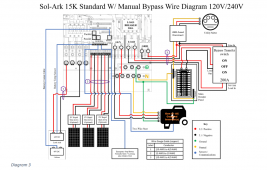
Can anyone comment on the accuracy (or inaccuracy ) of this Solark Schematic with respect to the ground locations?
I think it is inaccurate, and shows the grounds in the incorrect locations.

I understand that if I insert a fused 200A disconnect switch between grid input/meter, and it is now "first" in line , the main bonded ground will need to be removed from the current location (inside my main 200a panel). I have also been informed that every single bare copper wire in the main panel will need to be removed from the neutral shared bus bar inside the panel, and a stand alone new bus bar will need to be installed inside my main panel, and all the ground wires located there.

I will also need to remove the two ground wires (one goes to my copper pipes, the other one goes out back to two ground rods) from the main panel and relocate same into the new fused disconnect.

Lastly in my case since my grid feed enters the back of my main panel, I will need to relocate my main panel about 6 inches to the left to allow access to the grid 200A input feed, as it is against code to add any polaris lugs or wire splices of that feed inside the main panel. I cannot even just take the existing wire and run it out the side of the panel, it needs to enter a stand alone distribution box of some kind.

Schematic from latest solark manual below for comment/feedback.

Lastly, if goal is to feed the main 200a meter feed to the fused disconnect, then the transfer switch, then the solark, then back to the main panel, won't that require using 4/0 Al wire for all those connections, as anything AL smaller than that will not support 200A.

Thanks for feedback, my install is getting more complex as I learn more about NEC code.

1659959948682.png
 
Can anyone comment on the accuracy (or inaccuracy ) of this Solark Schematic with respect to the ground locations?
I think it is inaccurate, and shows the grounds in the incorrect locations.

I understand that if I insert a fused 200A disconnect switch between grid input/meter, and it is now "first" in line , the main bonded ground will need to be removed from the current location (inside my main 200a panel). I have also been informed that every single bare copper wire in the main panel will need to be removed from the neutral shared bus bar inside the panel, and a stand alone new bus bar will need to be installed inside my main panel, and all the ground wires located there.

I will also need to remove the two ground wires (one goes to my copper pipes, the other one goes out back to two ground rods) from the main panel and relocate same into the new fused disconnect.

Lastly in my case since my grid feed enters the back of my main panel, I will need to relocate my main panel about 6 inches to the left to allow access to the grid 200A input feed, as it is against code to add any polaris lugs or wire splices of that feed inside the main panel. I cannot even just take the existing wire and run it out the side of the panel, it needs to enter a stand alone distribution box of some kind.

Schematic from latest solark manual below for comment/feedback.

Lastly, if goal is to feed the main 200a meter feed to the fused disconnect, then the transfer switch, then the solark, then back to the main panel, won't that require using 4/0 Al wire for all those connections, as anything AL smaller than that will not support 200A.

Thanks for feedback, my install is getting more complex as I learn more about NEC code.

View attachment 105895
I called Sol-ark with this exact question since their manual indicates the ground neutral bond at the main panel instead of the first disconnecting means. They said that they would recommend placing it at the first disconnect instead of what the manual says. So yes all the ground wires currently on your neutral/ground bus bar need to be relocated to a separate ground bar in your main panel. Don't forget to remove the green grounding screw out on your neutral bus bar as well.

Edit: 4/0 Aluminum or 2/0 copper for 200A
 
Last edited:
I don't see the need/benefit of moving neutral/ground bond from breaker panel to disconnect.
Maybe code requires it, maybe not, but I don't know why it should.

I could have an isolated inverter/generator feeding a breaker panel that contains neutral-ground bond.
Or, inverter/generator could provide the bond, and breaker panel keeps them isolated?
Seems to me, grid, service entrance, disconnect switch is no difference.
Only L1 and L2 are being disconnected. Neutral feeds through the switch. Ground feeds through the switch. Works the same wherever bonding occurs.
The meter itself is a disconnect switch; utility can unplug it. Does that mean neutral/ground bond is required to occur inside or prior to meter socket?
 
Back
Top