Try a higher value like 100WThe grid 200a main power from meter is connected to grid input on solark.
The main home panel with all loads is connected to the load output on the solark.
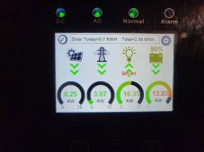
I don't have any DC PV At this time.
The Solark CTS are monitoring the 200A feed from meter to Solark and Agree with my meter for current incoming or exiting my home.
Sorry for any confusion.
I am adjusting the grid sell amount to see if that helps. Set at 20w appeared to work for periods of time from the logs I have.


You are using an out of date browser. It may not display this or other websites correctly.
You should upgrade or use an alternative browser.
You should upgrade or use an alternative browser.
Sol-Ark 15K All in One Inverter Released.
- Thread starter robby
- Start date
robby
Photon Vampire
- Joined
- May 1, 2021
- Messages
- 4,119
Yes and also see if your CT's are optimally positioned.Try a higher value like 100W
It can only work as well as the CT info it is getting.
Hedges
I See Electromagnetic Fields!
- Joined
- Mar 28, 2020
- Messages
- 20,632
I don't have any DC PV At this time.
The Solark CTS are monitoring the 200A feed from meter to Solark and Agree with my meter for current incoming or exiting my home.
Only AC coupled, in which case all it can do is detect backfeed and disconnect the GT PV.
(off-grid it may control with frequency shift.)
I think SolArk recommends DC > AC coupled, which would let them ramp DC coupled up & down, shed AC coupled as needed.
Getting permission to connect and backfeed would be the best thing to do. Then look into DC coupled. That may require RSD, or maybe you can avoid that if PV panels not on house.
Thanks to all for the replies.. I will keep investigating, but Second battery is going in, and perhaps I can run on grid all day fill both batteries to the top, then run them down overnight off grid, and run the batteries back down, and minimize the AC coupled PV sent back to the grid.Only AC coupled, in which case all it can do is detect backfeed and disconnect the GT PV.
(off-grid it may control with frequency shift.)
I think SolArk recommends DC > AC coupled, which would let them ramp DC coupled up & down, shed AC coupled as needed.
Getting permission to connect and backfeed would be the best thing to do. Then look into DC coupled. That may require RSD, or maybe you can avoid that if PV panels not on house.
The idiots at my local electric company replied after 8 business days that my 9.8 KW (post losses) AC coupled PV is now deemed to be > 10Kw power source since the Solark is labeled 15Kw so all my techincal details won't be looked at by engineering until I send in a Level 2 interconnect request for PV > 10KW and another $165 for the higher interconnect permission. I explained how the current setup doesn't involve the Solark doing any PV-AC conversion, and my current array is < 10Kw on at least 3 occasions but the same guy has no replied twice over the past 30 days requesting I send more $ and the paperwork for > 10Kw PV interconnect. So his view is potential interconnect PV from the Sol-ark is the deciding factor, which is a little silly , and factually incorrect in my view.
Sigh.. oh well.. at least I can run off grid and minimize my bill while the clowns run me in circle of nonsense about how a15Kw label on the Solark increases my PV sent to the grid.
As of now there doesn't appear to be any Sol-ark setting that will stop sending large amounts of power to grid. I made the grid sell 100W and when operating "on grid" once battery is 100% full, it sends 100% of the excess power to grid. Only turns off the PV based on battery level when "off grid".. Not sure that is the design intent, will see what Sol-ark tech support has to say. My main power cutoff is now off to avoid sending power to grid, with full battery.
Last edited:
Hedges
I See Electromagnetic Fields!
- Joined
- Mar 28, 2020
- Messages
- 20,632
Rip out the SolArk and get permission to operate with just your microinverters? You know, the only thing that has PV panels?
After their tail lights disappear from view, SolArk programmed for 10kW export limit would never exceed that.
After their tail lights disappear from view, SolArk programmed for 10kW export limit would never exceed that.
Whine OnRip out the SolArk and get permission to operate with just your microinverters? You know, the only thing that has PV panels?
After their tail lights disappear from view, SolArk programmed for 10kW export limit would never exceed that.b
-------------------------
I've sent emails telling the exact same guy something similar, he is just too dense to understand how I am using the Sol-ark. They also sent me approval for Level 1 operation 1 month ago, then said ooops.. Sorry, we sent you someone elses approval, you still have hoops to jump through. I asked for a zoom meeting or a brief phone call.. no dice, we only speak to the serf's (customers) via email, every 5 or 6 working days for each reply, with one more minor detail you have to correct/fix/address.
Oh and by the way our agreement to pay you for your excess generation doesn't apply since you are not using us for your power, just the delivery. And no your less expensive supplier will just laugh when you ask them if they will pay for excess power your PV generates. Senator Bob in the State Senate approved that minor change in the tariffs over an expensive bottle of wine and a large FIlet Mignon last year.
And Gee it is a 15Kw inverter sir.. what does programming mean? It's not inverting any PV ? But it's labeled 15Kw inverter so you are level 2, not level 1.
And each email back and forth has 5-8 working days of further delay, so I have surrendered and will send them the extra $165 in fee's and a level 2 interconnect . This of course will be snail mail so.. well you get the picture..
--------------------------
Whine off.

I would take that approach, but if/when they ever come to install 2 way meter, they may demand to come inside and observe what I have installed. If they see the Sol-ark they might get cranky. Who knows.
Last edited:
Hello All..so I have my first 280Ah 16 cell home built battery installed, and have set up time of use to use battery when sun goes down. Others have pointed out that the SOC on the Sol-Ark is not very good. Last evening my Sol-ark reported an instant drop from 45% to 0%, and I investigated what was up. Goal is to have the SOC on the Sol-ark disconnect from the battery, FIRST, then wait until sun comes up and recharge. This setup is recommended by Sol-ark. problem is when the Sol-Ark thought the battery was at 45% SOC, it was actually very nearly dead (based on the voltage log below).
The JK BMS is set to disable discharge whenever it sees <47V. So in this case the BMS shut down the battery discharge, and when that represents 0% SOC.
When I compare current SOC, as the battery is charging up, the Sol-ark is reporting 18% and the JK BMS is also reporting 18%. Prior comparisons showed differences where the Sol-ark reports 65% , and the JK BMS reported 45% so the Sol-Ark appears to be reporting a higher SOC in general, but to go from 45% to 0% when the battery is near dead is pretty awful.
This event was triggered by 4 days of crappy cloudy weather where my single battery never got about about 55-65% SOC.
Goal is to have Sol-ark disable discharge when it sees 20% SOC (that is programmed into Sol-Ark) and battery empty is also programmed at 47V.
If the battery is empty, and Sol-ark thinks it is still at 45% SOC, then the BMS cut-off is hit, that is not what I need/want.
Suggestions? Switch SOC to V instead of %? Other parameters to set?
Attached below are the Sol-ark SOC, and V charts for the event described.
Thanks in advance for any suggestions.
6
629658
Guest
I just program my Sol Ark to grid charge to 100% and then the SOC on the Sol Ark will match the battery BMS. You can play around with your total battery bank size in the Sol Ark to get a better match. I see mine get off by 10% or so with cloudy days but I always charge between 1-3am so they are back synced up by morning.
robby
Photon Vampire
- Joined
- May 1, 2021
- Messages
- 4,119
Sol-Arks algorithm for calculating SOC is just not that good once you get two or three consecutive days of low charge.
Using Batt-V mode at least insures that you won't deplete the battery past a safe point.
I have talked to a top engineer at Sol-Ark about this issue and he said it is impossible to keep the reading from drifiting because of all the different brands of battery people are using and other things like Temperature changes and battery age. Basically they have found no one all encompassing algorithm that works reliably.
It can calibrate itself and work properly for a time once it gets a full charge but then the drift starts to happen if a full charge is not happening on a regular basis.
This is why they stress using a closed loop system and not open. I had very little issues in the Summer but now that the days are shorter, the Sun has gone lower and the weather gets more erratic I am noticing this problem more and more. It is probably going to be time for me to dump Solar Assistant and connect back my closed loop system.
robby
Photon Vampire
- Joined
- May 1, 2021
- Messages
- 4,119
The inverter is reading both those values so I would assume they are used in the calculations. One issue I can see is that the current and therefore capacity change based on the temperature when it is discharging.Their algorithm needs to use the battery voltage and current as part of the input
If can have my absorption voltage set at 56V and the Sol-Ark will tell me I hit 100% SoC at below 54V. If they take battery voltage into account then they aren't doing it well lolThe inverter is reading both those values so I would assume they are used in the calculations. One issue I can see is that the current and therefore capacity change based on the temperature when it is discharging.
6
629658
Guest
With Lithium Iron Phosphate the voltage drop is not linear that’s the problem so calculated SOC cannot be determined by voltage alone
Steve s from Canada published a pretty detailed spreadsheet showing SOC versus voltage. I realize there are error bars on that information but I don't understand why I can't look at my JK BMS when it thinks it's 100% charged or 15% charged and use that voltage in the sol-arc to obtain +- 10% accuracy. I know the discharge curve is pretty flat but curve fitting has been around for a long long time.
I was pretty shocked that the sol-arc after 4 days of crappy PV weather thought the battery was at 45% when in fact it was near zero.
But I'm learning and folks here are confirming that that's what happens when it doesn't go back to 100%.
I don't expect perfection but that's pretty bad.
Rob sorry for displaying my ignorance but can you share what you mean by closed loop system.
6
629658
Guest
That is the main reason I have Solar Assistant. At least I know what my true SOC is. I also have a Victron shunt installed and it get fooled too by short charge cycles. So it’s just the nature of the beast. As long as I know when it’s going to occur I can compensate. Even if the Sol Ark had closed comms with my batteries I’m not sure I’d give up the Solar Assistant it offers so many side benefits and detailed cell by cell battery info.
robby
Photon Vampire
- Joined
- May 1, 2021
- Messages
- 4,119
I have seen the same 40%+ out of range value on mine of late.Steve s from Canada published a pretty detailed spreadsheet showing SOC versus voltage. I realize there are error bars on that information but I don't understand why I can't look at my JK BMS when it thinks it's 100% charged or 15% charged and use that voltage in the sol-arc to obtain +- 10% accuracy. I know the discharge curve is pretty flat but curve fitting has been around for a long long time.
I was pretty shocked that the sol-arc after 4 days of crappy PV weather thought the battery was at 45% when in fact it was near zero.
But I'm learning and folks here are confirming that that's what happens when it doesn't go back to 100%.
I don't expect perfection but that's pretty bad.
Rob sorry for displaying my ignorance but can you share what you mean by closed loop system.
During my first Winter I had only 15KWh of batteries and in the Summer I had 26KWh so I was only seeing about 10% drift at the most.
This Winter with 26KWh I am seeing the same kind of issues that a few others reported. The Drift increases with each day of bad weather and only resets to proper values when you get a full charge.
Forget Voltage when trying to accurately determine SOC.
I can read 54V when my batteries are only at 56% SOC. Think of it this way, (Trying to keep this simple cause we have Ions in the mix also) the charging has filled the waiting room full of Electrons that are not yet seated so if you put a meter across the terminals you are reading the backed up electrons flowing from the Anode as well as the ones that have been deposited on the Cathode electrodes.
Remove the charge and the waiting room empties very quickly and the voltage quickly drops until it starts to reflect the ones seated on the Cathode electrode and the empty spots on the Anode. This is why when you stop charging the battery the voltage will drop from 54-55V down to 53.4V The ones not yet seated are finding seats and the charging voltage from the inverter is removed from the equation.
This still does not mean the battery is fully charged as there may be more seating Capacity available. It's not until you the cell itself starts to taper off the amount of current it is drawing that you truly know all the seats are taken.
The only critical thing about voltage is that you need to make sure it is not to high and you need to know that it does not drop to low. You cannot have a Low voltage and still have lots of electrons still on the Cathodes.
When an inverter has to deal with multiple battery packs that also contain multiple cells you can see how the problem of accuracy can grow even faster.
Closed loop is when the Inverter and battery BMS are connected together through a data cable. The battery lets the Inverter know what it's SOC is. When multiple battery packs are connected to the Inverter it can simply average out the SOC of all the Packs and does not have to worry about keeping track of how much energy is in each pack.
Last edited:
Thanks closed loop makes perfect sense now. Wonder if anyone out there is working on JK BMS to Solark speak. Beyond my limited programming ability LoL. Thanks for the detailed reply. Once I get my two way meter installed I can use some of my excess PV to grid to grid top off after 3-4 days of crappy PV weather.?I have seen the same 40%+ out of range value on mine of late.
During my first Winter I had only 15KWh of batteries and in the Summer I had 26KWh so I was only seeing about 10% drift at the most.
This Winter with 26KWh I am seeing the same kind of issues that a few others reported. The Drift increases with each day of bad weather and only resets to proper values when you get a full charge.
Forget Voltage when trying to accurately determine SOC.
I can read 54V when my batteries are only at 56% SOC. Think of it this way, (Trying to keep this simple cause we have Ions in the mix also) the charging has filled the waiting room full of Electrons that are not yet seated so if you put a meter across the terminals you are reading the backed up electrons flowing from the Anode as well as the ones that have been deposited on the Cathode electrodes.
Remove the charge and the waiting room empties very quickly and the voltage quickly drops until it starts to reflect the ones seated on the Cathode electrode and the empty spots on the Anode. This is why when you stop charging the battery the voltage will drop from 54-55V down to 53.4V The ones not yet seated are finding seats and the charging voltage from the inverter is removed from the equation.
This still does not mean the battery is fully charged as there may be more seating Capacity available. It's not until you the cell itself starts to taper off the amount of current it is drawing that you truly know all the seats are taken.
The only critical thing about voltage is that you need to make sure it is not to high and you need to know that it does not drop to low. You cannot have a Low voltage and still have lots of electrons still on the Cathodes.
When an inverter has to deal with multiple battery packs that also contain multiple cells you can see how the problem of accuracy can grow even faster.
Closed loop is when the Inverter and battery BMS are connected together through a data cable. The battery lets the Inverter know what it's SOC is. When multiple battery packs are connected to the Inverter it can simply average out the SOC of all the Packs and does not have to worry about keeping track of how much energy is in each pack.
MaikaiLifeDIY
Solar Enthusiast
So I understand, you have both the negative and positive fused? I'm looking to hookup a sol-ark 15K to two Eg4 racks of batteries and I was just thinking about using 1x Lynx Distributor. Only hot is fused and it's technically double fused, but I presume it should work and simply things?Got it. I know there are a few differences dc vs ac coupled. You sound frustrated and I understand. Being a grid tied guy for 8 yrs our new Sol Ark is amazing and functioning better than I expected. But that is our experience. Tech support from Sol Ark has also been extremely good.
Now to your battery connections. Here is what I did. I installed two Lynx Power Ins to use as my fusible buss bars. I ran two sets of 4/0 from inverter to the Lynx buss. Landed one set on each end of the busses. Then I ran individual equal length cables from each battery to the buss. I installed 300A 48v mega fuses on each battery positive lead. Works very well and is very safe. Lynx is rated at 1000A. Just my way of doing it.
Here is a way to save $50-60 over the Lynx distributors.

Only fusing either the + or - is pretty commonSo I understand, you have both the negative and positive fused? I'm looking to hookup a sol-ark 15K to two Eg4 racks of batteries and I was just thinking about using 1x Lynx Distributor. Only hot is fused and it's technically double fused, but I presume it should work and simply things?
View attachment 121345
Similar threads
- Replies
- 4
- Views
- 178
- Replies
- 14
- Views
- 1K
- Replies
- 17
- Views
- 740