Let me run a few tests over the weekend and I’ll make some pretty charts."balancing" by BMS would be equalizing voltage between cells within a single battery. You should be able to read cell voltages from it.
Diagonal corners should be perfect for two batteries, not exactly perfect for more. If yours discharge within a couple percent of each other, should be good enough. Was that in the flat part of the curve? I'd expect it to balance out SoC at the top and bottom knees (currents diverging as needed to maintain similar voltage).
You are using an out of date browser. It may not display this or other websites correctly.
You should upgrade or use an alternative browser.
You should upgrade or use an alternative browser.
Sol-Ark 15K in Operation--my thoughts on install and communication
- Thread starter kdub23
- Start date
Not Aerosmith
Solar Enthusiast
- Joined
- Sep 8, 2022
- Messages
- 389
Very impressive setup!!! Excellent in every detail!!!Hi All,
Last Friday, I put my Sol-Ark 15K into production. This was a retrofit into an existing 18kw grid-tied system. For now, I exclusively AC-coupled, but will reconfigure once my garage gets to a more palatable temperature to DC-couple the Sol-Ark with ~12kw of my capacity. I also got the 15K talking via MODBUS RTU. Here are my thoughts on installation/operation and some notes on speaking MODBUS.
View attachment 105985
INSTALLATION:
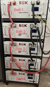
As mentioned, I AC-coupled for now, but will adapt in the future to allow myself the ability to preferentially choose what system I will use for PV inversion. With the 200-amp contactor, I ran my entire household through the 15K. This is teamed up with 5x SOK SK48v100 Rack Mount LiFePO4 batteries from the guys at CurrentConnected.
COMMUNICATION:
- I mounted the Sol-Ark (all 138 lbs of her) ~6" over a 12"x12"x60" wire trough. I paper-traced the knockouts and transferred those down to punch out. I used EMT with set screw connectors. Even with ample 1-1/2" knockouts and (currently) no PV wire connected, the connection area gets tight. The ground and neutral bars need either crimped on ring connectors or lugs (what I used) to land those. This makes the right-hand side of the unit pretty congested. Sol-Ark went with a 1" knockout instead of 1-1/2" for the communications, so plan ahead if you don't have a partial stick of that laying around.
- Some issues:
- The manual (as discussed at length here on the forum) is not well done. Upon first flipping the disconnect, you're kinda left at a loss for what to expect from the unit, especially when your loads don't immediately turn on.
- The protective film on the screen is amazingly hard to remove!
- The plastic cover to keep your conductive little fingers from getting where they shouldn't be does not have a large enough cutout for the battery breakers. That means you can't secure it flush and it bows out right around those breakers. How do you miss that??
- If you use 4/0 battery cable like me, getting both through the toroids was a little difficult.
- Adding the WiFi/Ethernet dongle and setting up the app is cumbersome at best. The app asks for your address and phone number and that's a big ole nope from me, especially noting that I had to allow previously blocked connections to/from China through my firewall to get the dongle to work.
- Updating firmware for the Sol-Ark was painless, but it's a weird process. You request it from their site and a nice support engineer reviews that request and pushes that firmware to you. I checked the box for automatic updates during that process before I realized that when the firmware update is applied, the inverter restarts and cuts power to your loads!
- The fan is louder than I expected. It also comes on randomly in my hot garage even though it is not performing any meaningful DC-to-AC conversion. It doesn't come on in the morning when the garage is cooler.
- My SOK batteries are awesome. They immediately communicated with the Sol-Ark with no fuss. Straight ethernet cable and one settings change, and you're speaking CanBus. As you can see in my picture, the battery lugs are not only prominently presented, but also uncovered. An errant brush with a shovel or weedeater shaft, and some sparkies will ensue. I've 3D-printed off some battery lug covers, but still tweaking a few dimensions on those.
- Overall, it's impressive what this hunk of electronics they call the 15K can do. Failover to battery involves the slightest flicker from your lights. Anything with capacitors will not even realize the power is no longer coming from the grid. It successfully started (albeit with some strain) my 4-ton upstairs A/C while running the downstairs heatpump and the rest of the house. Impressive indeed. Grid-tying was painless, although the 5-minute countdown from my Sunny Boys will get annoying.
Let me know if you guys have any questions or want to see anything else. Appreciate all the advice I got on here before embarking on this install. I've still more things to play with, but so far I'm pretty happy with what I've done.
- The PVPro app is better than I expected, but as mentioned several times before, being so reliant on the PRC for data/apps is a big turnoff. Politics aside, I'd rather have faith that even my seemingly innocuous data is staying safe. Yes, there is only a 5-minute refresh rate, but more on that in a second.
- With a lithium battery in place, you can speak MODBUS RTU over half-duplex RS-485. Since I already had a WattNode Modbus in my main panel, I can easily daisy chain the Sol-Ark with my WattNode and let the datalogger poll both of them. The Sol-Ark supposedly cannot change its address to anything other than 1 unless in a parallel application. Using the Modbus document posted on these forums, I was able to rapidly communicate and pull data from the Sol-Ark.
- Most parameters update every second, however, totals seem to update every 5 minutes which may tie to the app update interval.
- The Sol-Ark totals differ slightly from my SMA and WattNode readings. I've verified the SMA and WattNode to being damn-near revenue grade, so I'm thinking accuracy isn't the highest with the Sol-Ark, but time will tell when I get my analytics and dashboard built.
robby
Photon Vampire
- Joined
- May 1, 2021
- Messages
- 4,118
Yes but there are some major communication advantages that are had when the Sol-Ark is directing the port to a specific subroutine designed for a battery pack that is integrated into the Sol-Ark firmware.I assume in any other mode, the Sol-Ark becomes a Modbus Master and therefore does the polling and cannot be polled as a slave device. Unfortunate. (And also one of the reasons I chose SOK.)
400bird
Solar Wizard
I'm glad you moved the battery cables to 2&4, that helps even the usage on batteries 2, 3, and 4.
But 1 and 5 have double the cable length and connections compared to 2-4
You really should move the cables to 1 and 5, not 2 and 4.
Count the short battery cables (positive and negative) that are between the inverter connections and each pack.
With the original set up, both inverter cables one batt 1, there were 0 short cables involved. Lowest resistance.
Batt 2 had two short cables in the current path. One positive and one negative.
All the way down to batt 5 that had 8 short cables in the current path and th highest resistance.
With the battery cables on 2 and 4, batteries 2-4 have 2 short cables in the current path. While batteries 1 and 5 have 4 short cables.
If you move the inverter connections to 1&5, each battery has 4 short cables in the current path.
I only mentioned the short cables, but the same applies to the posts on each battery and internal bus bar.
The thread I linked earlier has a great discussion on paralleling multiple batteries and is certainly worth a read.
Ultimately, EE and forum member Solarod came up with what's likely about the best balance you're going to get for a 5 pack battery. Note busbars would be required, but looks like it would be easy to implement in the OP's 5 battery stack. Here's a direct link for 5 batteries:

 diysolarforum.com
Ultimately, EE and forum member Solarod came up with what's likely about the best balance you're going to get for a 5 pack battery. Note busbars would be required, but looks like it would be easy to implement in the OP's 5 battery stack. Here's a direct link for 5 batteries:

Calculation of parallel string battery currents
Can your mathematical model confirm that wiring each battery to a common bus bar, using equal length cables to each battery, provides a balanced charge/discharge?
@Wet1 @400bird @HedgesThe thread I linked earlier has a great discussion on paralleling multiple batteries and is certainly worth a read.
Ultimately, EE and forum member Solarod came up with what's likely about the best balance you're going to get for a 5 pack battery. Note busbars would be required, but looks like it would be easy to implement in the OP's 5 battery stack. Here's a direct link for 5 batteries:

Calculation of parallel string battery currents
Can your mathematical model confirm that wiring each battery to a common bus bar, using equal length cables to each battery, provides a balanced charge/discharge?diysolarforum.com
Okay, I shut my solar off this morning on a bright, crisp day on the homestead...went inside and turned dryers and ovens on to draw my batteries down and subsequently charge them back to 100%. I had my Campbell Scientific logger polling all 5 batteries at 30 second intervals capturing several parameters from the BMS(s).
First, here is the setup:

Now to the charts. I pulled the batteries down to 60% and charged them back using solar at ~175Amps as I'm only using one of the SolArk's battery terminals at present.
Here are my starting capacities:
| Battery 1 | 102.91Ah |
| Battery 2 | 103.92Ah |
| Battery 3 | 103.46Ah |
| Battery 4 | 103.73Ah |
| Battery 5 | 102.42Ah |
| TOTAL | 516.44Ah |
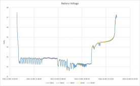
As expected, voltage across packs remained very consistent:

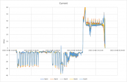
A little difference starts showing up in current as battery 2 and battery 4 are at a higher magnitude than the other three:

But we're talking an amp or two overall. So, looking at an overall drawdown:

This plot shows the Battery 2 clearly did the most work with the other 4 closely lumped together until the last 15ah or so of charging.
So in summary:
| Batt | Starting Capacity | Drawdown |
|---|---|---|
| Battery 1 | 102.91Ah | 40.04Ah |
| Battery 2 | 103.92Ah | 41.61Ah |
| Battery 3 | 103.46Ah | 39.97Ah |
| Battery 4 | 103.73Ah | 40.23Ah |
| Battery 5 | 102.42Ah | 40.29Ah |
| TOTAL | 516.44Ah | Min:39.97 Max: 41.61 Diff: 1.64Ah |
Observations:
- Battery 3 contributed the least despite it being only 2 jumpers away from the leads
- Only 1.64Ah difference in packs
- The SolArk's 200Amp battery breakers work fantastically
- The BMS's don't appear to coordinate current between batteries other than in pre-charge scenarios
- My 4/0 jumpers between batteries don't appear to be a big bottleneck
- The difference probably isn't enough to get me to change the battery cable configuration.
400bird
Solar Wizard
Seems like you have talked yourself into leaving them as is.
There's always going to be some difference in internal resistance, but we don't need to create preference in our builds
There's always going to be some difference in internal resistance, but we don't need to create preference in our builds
That's not something any BMS can do. The BMS is all or nothing. It can open the MOSFETs, but there's no way for the BMS to compare current and even out the load.
- The BMS's don't appear to coordinate current between batteries other than in pre-charge scenarios
The SOK's have a feature, well, just better to quote:Seems like you have talked yourself into leaving them as is.
There's always going to be some difference in internal resistance, but we don't need to create preference in our builds
That's not something any BMS can do. The BMS is all or nothing. It can open the MOSFETs, but there's no way for the BMS to compare current and even out the load.
Didn't know if this extended to normal charging or even discharging scenarios. It was, admittedly, wishful thinking.The battery can only accept 100a charge current max. In a multi-pack system, the current entering the battery can exceed 100a if the packs are out of balance or wiring is not designed to share current evenly. a limiting circuit is activated that will restrict the charge current to 10a. This is especially useful when connecting multiple packs in parallel at varying states of charge. The 10a of current allows the battery to reach a higher state of charge before re-enabling full charge current.
Hedges
I See Electromagnetic Fields!
- Joined
- Mar 28, 2020
- Messages
- 20,600
- Battery 3 contributed the least despite it being only 2 jumpers away from the leads
Looks to me like Battery 3 was very close to the others.
Outlier was Battery 2 contributing 1.3 Ah (3%) more than the others.
6
629658
Guest
Power View is nothing but eye candy. Lots of data but absolutely no way to export it for serious examination and review. Used to be able to get data off in 7 day increments but that’s gone now too. 5 min refresh rates suck too. Complete crap in my book. Solar Assistant is better and at least I can have access to my dataPowerview Pro (Web Version) is really a well written piece of software. I suspect that not many Sol-Ark owners have dug into it to see how powerful it really is. I think I counted 69 Parameters that can be graphed 6 at a time on an overlay and it keeps all the data saved from day one.
I shaved of at least 10% of extra grid usage just by studying the graphs and tweaking the TOU and then seeing the results after a week then tweaking further and further until every last drop of power that can offset the grid is used while still keeping me safe from a blackout.
Quattrohead
Solar Wizard
Solar assistant is great but if you don't have a raspberry pi in your stash you are screwed right now. There is not a single one of those available in the whole world from what I can find unless you want to pay enormously jacked up prices and that is not what raspberry pies are all about.
6
629658
Guest
This is what mine is running on. Works great and $52 on Amazon. Orange Pi 3 LTS Allwinner H6 2GB LPDDR3 8GB EMMC Flash Quad Core 64 Bit Single Board Computer 5V3A Type-C Support Android 9.0, Ubuntu, Debian Mini PC (PI3 LTS+ Type-C Power Supply+Al Heat Sink+case) https://a.co/d/in2AvQY
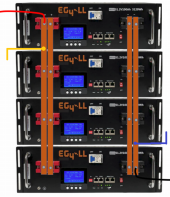
Would connecting batteries to a busbar fix this issue in the case of 4 batteries?"balancing" by BMS would be equalizing voltage between cells within a single battery. You should be able to read cell voltages from it.
Diagonal corners should be perfect for two batteries, not exactly perfect for more. If yours discharge within a couple percent of each other, should be good enough. Was that in the flat part of the curve? I'd expect it to balance out SoC at the top and bottom knees (currents diverging as needed to maintain similar voltage).
6
629658
Guest
Busbars will even out charge/discharge of individual batteries in multiple battery installs. It keeps voltage losses and energy efficiency higherWould connecting batteries to a busbar fix this issue in the case of 4 batteries?
Hedges
I See Electromagnetic Fields!
- Joined
- Mar 28, 2020
- Messages
- 20,600
Busbar that is larger than cables should be an improvement. Four matched cables to short busbar is another. Diagonal connection helps.
For 4 batteries, you can do two pairs, diagonally connect them to group of 4, diagonally connect that to inverter.
Perfection of matching matters more for lead-acid, where lower SoC means more rapid degradation.
For Lithium, I think matched resistance is more about distributing current draw (if total is more than one BMS can handle) and equalizing usage/wear. It may be that pretty good is good enough.
Even a wiring configuration that is perfect will likely have some imbalance due to battery differences. Just do as decent a job as reasonable.
In AC wiring (multiple inverters with bypass relays in parallel) I had 3:1 imbalance due to circuit breaker differences. Changed models and now balanced within 10%. The (long) perfectly matched wires were good enough except when I had a poor connection (cross-threaded nut on split bolt.)
Thank you. I have 4 lithium 48v 200ah powerwall type batteries. They all have the same length of 4/0 cable, going to a copper busbar in a battery combiner box with breaker. Right now I have some imbalances, but they are inconsistent, meaning one day Batt #1 will be 2% less than the others, the following day it could be any of the other three that are less. I'm going to use the BMS computer software, provided by the manufacturer of the batteries, to deplete them completely and rebalance them. Hopefully this will solve the issue. If not, I may be back to ask some more questions.Busbar that is larger than cables should be an improvement. Four matched cables to short busbar is another. Diagonal connection helps.
For 4 batteries, you can do two pairs, diagonally connect them to group of 4, diagonally connect that to inverter.
Perfection of matching matters more for lead-acid, where lower SoC means more rapid degradation.
For Lithium, I think matched resistance is more about distributing current draw (if total is more than one BMS can handle) and equalizing usage/wear. It may be that pretty good is good enough.
Even a wiring configuration that is perfect will likely have some imbalance due to battery differences. Just do as decent a job as reasonable.
In AC wiring (multiple inverters with bypass relays in parallel) I had 3:1 imbalance due to circuit breaker differences. Changed models and now balanced within 10%. The (long) perfectly matched wires were good enough except when I had a poor connection (cross-threaded nut on split bolt.)
Hedges
I See Electromagnetic Fields!
- Joined
- Mar 28, 2020
- Messages
- 20,600
BMS should keep the 16s cells within a single battery balanced.
Recharging the bank of 4 past the knee, and holding at a voltage letting them each balance and all tail off in current for a while, should bring the four to same SoC.
I don't think depleting and rebalancing individually is any benefit.
Within 2% of each other in terms of SoC or current sounds very good.
Does your current draw exceed what one BMS could supply? Does imbalance ever bring a BMS close to disconnecting?
Once in the last 4 months, yes. Not normally.BMS should keep the 16s cells within a single battery balanced.
Recharging the bank of 4 past the knee, and holding at a voltage letting them each balance and all tail off in current for a while, should bring the four to same SoC.
I don't think depleting and rebalancing individually is any benefit.
Within 2% of each other in terms of SoC or current sounds very good.
Does your current draw exceed what one BMS could supply?
No. Lowest discharge has been -/+ 65% across all 4 batteries. If normal weather (NM with TONS of sun with the exception of this summer of 5 mos of rain), my normal discharge is only when sun isn't shining (I'm totally off grid currently) and is normally only down to 85%SOC.Does imbalance ever bring a BMS close to disconnecting?
Similar threads
- Replies
- 4
- Views
- 173
- Replies
- 17
- Views
- 736
- Replies
- 0
- Views
- 166


