diy solar

diy solar

Sol-Ark 15k will only invert 13k of DC PV to AC

Both wires should reduce heating. I don't know how much would occur with a single wire (would be an interesting experiment).
If provided by manufacturer to be installed in a particular way, it should be fine used that way.
(Of course we never know how thoroughly it was engineered or tested. Ferrites around cables are usually done after an EMI test fails, just before certification and shipping.)
 
Yes, good to have ferrite close to inverter (rather than close to battery), and put it around both positive and negative so it reduces radiated RF power.

Two separate issues:

1) If the inverter generates common-mode noise on the wires, that radiates. Assuming the ferrite is effective blocking the noise, the length of cables from inverter to ferrites is what acts as an antenna, so ferrite closer to inverter is more effective.

2) AC current in wire causes changing magnetic field, which the ferrite attempts to oppose. The ferrite is suppose to do this by storing and returning energy (an inductor) but also dissipates some power so could get hot with large AC current.

The ferrite is quite small compared to a power transformer, can store very little energy before it "saturates" (becomes as strong a permanent magnet as it is able to be.) A small current through it, and it can be magnetized first with one polarity then with the other; that works as an inductor. Once it is fully magnetized (all the atoms' spinning electrons are oriented one way) it ceases to absorb magnetic field from the wire, and current flows unimpeded. The current to saturate could be on the order of milliamps.

With 100A DC flowing through a cable, the ferrite would saturate and be useless. With positive and negative cables through it, The sum of +100A and -100A = 0A, no net current and the DC current (and any differential current) cancel and don't interact with the ferrite.

What the ferrite can do is block common mode current (only if differential mode is canceled by having both wires go through it.) If both battery terminals are swinging up and down together in voltage, and the battery is not (relative to earth), current will propagate as a wave. Just like in the antenna of a radio transmitter. Just like a digital signal in a wire, over a ground plane. Often, wires used to carry data are dimensioned to have 50 ohms characteristic impedance. The pair of battery cables dangling in the air (small diameter and far above the ground) could be more like 100 ohms, just a guess. Consider if the battery terminals have 1V RMS common mode on them. That is, negative is at zero volts and swings +/-1.4V, positive is at 48V +/-1.4V. 1Vrms/100 ohms = 10 mArms. That is what the ferrite sees, and its impedance reduces the voltage amplitude on the cable after it. Maybe zero +/-0.1V and 48V +/-0.1V, so less power is transmitted.

That was about preventing radiated power from an electric "E field" antenna.

3) Third issue, preventing radiated power from a magnetic "B field" antenna:
Current flowing in a loop is differential, and radiates power. That depends on how large the current is, and how much loop area. If you lay the positive and negative wires a foot apart, there is several square feet of area. The 100A DC current doesn't matter (makes a DC magnetic field) but the pulses of current drawn by switcher, to the extent not filtered by capacitors, are AC current in the wires. Choke can't help that. Inductors in the inverter design may help. Twisting the wires reduces loop area (and positive to the left, negative to the right for one twist cancels filed from negative to the left, positive to the right of next twist, at a distance.) Batteries themselves form a loop; if you were really trying to minimize radiated power, might arrange batteries so they also form a twisted loop.

For the most part, minimizing differential current is the job of inverter designer. Simply cable tying positive and negative together should be good, or twist if easy.


Different topic, those cable terminals are exposed and close. Make sure they can't come in contact. A piece of of insulation between them might be good.
I have a follow up to this. Please pardon my ignorance on this.
What about the the DC current coming from the Solar Panels into the inverter? From what you're saying, it seems like there would also be an issue with AC current interfering with the DC wires/current from the Solar Panels, or does this only depend on the number of Amps running through the PV dc wires?
 
@Dylan Hillman
And don't forget my issue with 12K. Similar problem.
 
Last edited:
I have a follow up to this. Please pardon my ignorance on this.
What about the the DC current coming from the Solar Panels into the inverter? From what you're saying, it seems like there would also be an issue with AC current interfering with the DC wires/current from the Solar Panels, or does this only depend on the number of Amps running through the PV dc wires?

DC current makes stationary magnetic field. Might confuse a compass but not interfere with radio.

The PV array makes a bigger loop antenna, and a bigger monopole, than the battery. AC differential current and common mode voltage would tend to radiate, so MPPT circuit has some filtering. Hopefully enough, and I haven't seen requirements to add ferrites externally (but haven't seen that for battery cables either in the equipment I've dealt with.)
 
@Clint-L
I am going to look into this issue and see if we can get to the bottom of it.
Here’s some pictures of the capping at just over 13kw of PV. I took these all within a couple minutes of one another. If I pull out any one of the three arrays, the other two arrays will show about 17 or more amps on each of their MPPTs respectively, which would equal about 15kw of active total PV at this time of the exercise. Each array alone can produce about 5Kw today with the irradiation happening on this day. Any time we add the third MPPT in to the mix, no matter which one, we see PV production cap out at about 14.5 per each MPPT equally. This is the facts and we can likely put the disconnecting from grid etc behind us, because the MCU update to 7.2.16 corrected that. Before that MCU update, we saw extreme voltage misreadings on the PV and on the AC L1/L2. That is not happening. Only issue now is the unit not producing amount of wattage inversion that it should.

72F46BAD-DAA7-41CD-9C92-5DB23E81587F.jpeg67ED59C2-EA4A-4E46-A4C4-08B7AAFF1150.jpeg
 

Attachments

  • 8B70F48D-D10D-4742-A9E3-D2BCFC9AFEC5.jpeg
    8B70F48D-D10D-4742-A9E3-D2BCFC9AFEC5.jpeg
    309.3 KB · Views: 4
I had a talk with Dylan and he said your problem is very real and very baffling to them. They are evidently trying to find out if it is a problem in the code that they missed. He says that his own 15K and others do not have the issue so they really want to know why yours does.
All I can tell you is that they are evidently working on it very hard but if you want to opt out of waiting you can probably just request a replacement.
It's up to you on how you want to proceed.
That’s good to hear
 
Once again, I'll post a screen shot of my 15K showing your problem is not universal. It is either a configuration issue or hardware problem.
 

Attachments

  • Screen Shot 2022-11-02 at 2.47.42 PM.png
    Screen Shot 2022-11-02 at 2.47.42 PM.png
    165.8 KB · Views: 44
Last edited:
I have a 15k with three arrays of DC PV connected to each of the three MPPT controllers. Each array can max output of 6,400 watts. So that is 19,200. The 15k specs state that it allows 19,500 of PV connected and will invert 15k max.

Here’s the problem- once the panels hit 13,200 that is the maximum and it clips / throttles all day with a perfect flat line. It absolutely will not invert 15k at this point.

Sol-Ark support has been working with us. They have updated software, reapplied update, and performed a full factory reset with no luck. Originally, the inverter would hit about 12k to 13k of PV power and literally disconnect from the grid. During the grid disconnect, we would see completely inaccurate reading of the VoC of the arrays. Voltages that were absolutely untrue. We were also checking with metering equipment and have never seen such a VoC spike. Nonetheless, It seems the software update corrected all of that. Sol-Ark support advised that they had seen some software issues with voltage misreading on the MPPT inputs we were seeing in the software as well as the inverter ramping up the output voltage to the grid too high, causing disconnect. I’ve seen both of these issues. Again, these were corrected not only with a software update, but a full reset of the unit.

As of the final software update and reset on 10-18-2022 we no longer see the grid disconnect. However, we are still seeing the clipping at 13k.

I really believe in the company and we are an installer and we have put in over 20 of the 12k units. However, I could not in good faith sell a 15k until this is addressed on our test unit.

Additionally, we are waiting to connect 19k of AC coupling through the AC coupling input, if Sol-Ark can address the PV DC inverting clipping / throttling issue.

I worry that Sol-Ark never tested this unit fully with the maximum PV specifications that they have published. Is anyone else out there seeing this, if you happen to have enough PV to see it max at 13k?


@Devin
@solark_cooper
@Will Prowse - do you have enough panels to do this same test?
Hi Clint,

Sorry to hear about the issue. We are currently
experiencing the identical problem here.
During initial testing we noticed some issues during peak solar and assumes the settings needed to be tweaked. For reference this sounds
like comparable setup but not identical.

Running this 15K with 19,200 ACC Coupled panels (SunPower 435w x44 with rebranded Enphase iq7+ micros) this setup was chosen specifically because of the published specs.
It was an existing grid tied Net system so maximum sell back to grid is the first objective.
On the DC side for now there is only 5k split up among the three MPPT inputs. That will be upgraded to approx 19k as long as this concern
can be remedied. Customer is quite upset at the
moment as she is losing production significantly
as every time the 15k disconnects it takes the Enphase micros 10 minutes to ramp back up.
After several drop outs it ruins the entire day of solar production. Initially SolArk advised adjusting to micros to phase shift to lower output. This seems like a bandaid, unfortunately
dealing with SunPower to adjust the micros has been difficult. Being told any modifications will result in the customers warranty being void. It really shouldn’t need to ramp them down provided the 15k can handle the listed rating.
Now in October it disconnects less frequently however it’s almost exactly as you described. Just past 13k ACC and it goes to zero. I’ve been pulling my hair out for weeks trying to find an adjustment to correct the situation short of reducing the ACC array. There were several other concerns than seem to be eliminated after the last firmware update but this issue just won’t go away. I should note this is likely an early production/demo unit so now I also wonder if it’s simply a hardware error. I could be here all day listing weird quirks that have been happening but
they may or may not be related and Id like to keep this post ON topic as I feel this could be an issue for others and so far Sol-Ark has not mentioned to me that this is a problem they have seen before? note: there is also a problem with TOU sometimes only allowing 750w 14.5aDC sell
Back, no matter the load on the inverter.
Oh I almost forgot to mention there is an open
loop lifepo bank of 45kWh. Which also has an issue maintaining correct SOC under heavy loads, or when charging over approx 0.2c.but that is for another thread.
Clint,
What do you think? Does this look familiar?
 

Attachments

  • 43F4476A-9E92-4827-BE0D-57EB425C93AA.png
    43F4476A-9E92-4827-BE0D-57EB425C93AA.png
    371.9 KB · Views: 29
  • 24DA389E-8736-4D9D-A5CA-8CAACCA32C7B.png
    24DA389E-8736-4D9D-A5CA-8CAACCA32C7B.png
    369.9 KB · Views: 29
Clint,
What do you think? Does this look familiar?
Similar yes.

I do not have any AC Coupling enabled currently. Trying to sort the issue out with solark.

I have closed loop EG4LL bank but I’ve unhooked it completely and had this problem occur before using closed loop when it was just configured with charge voltage manually.
 
Clint,
What do you think? Does this look familiar?
Not sure if I replied or not. Yes this is similar. It sounds like solark is hard at work on this, but this is terrible to have a customer going through it. The one I’m working on is at our shop, but we were originally just doing some proving out on a 15k because we had a customer that wants to put 19k DC and 19k ACC and we haven’t been able to get past the DC coupling yet. I sure hope the AC coupling isn’t going to be the same issue.
 
Once again, I'll post a screen shot of my 15K showing your problem is not universal. It is either a configuration issue or hardware problem.
Yeah I think @Clint-L should just box it up and send it back. No company has ever had a perfect record on the production line. It would be expected that 2-3 out of every 100 units they have produced have a hardware issue.
Sol-Ak has sold several hundred if not thousands of these units so it's not surprising that someone on this forum got a lemon.
Sol-Ark has made it pretty clear that they are willing to change or repair the unit so he should really take them up on the offer.
I feel like I agree. Mainly at this point just the amount of time I’ve spent. It’s kind of like, an easy thing is just let’s swap it out and see if the problem is corrected. We certainly won’t be in a worse place. ?
 
I feel like I agree. Mainly at this point just the amount of time I’ve spent. It’s kind of like, an easy thing is just let’s swap it out and see if the problem is corrected. We certainly won’t be in a worse place. ?
Hi,
Glad we are all on the same page here. Please don’t misunderstand me either because I read back what I wrote and it seems insensitive.
I’ll just say I love Sol-Ark. it’s an amazing product. Sol-Ark is years ahead of everyone else
and I don’t see that changing any time soon.
I also love Victron, but it apples to oranges.
I’m in a tight spot because I convinced a customer to stretch their budget to go with the
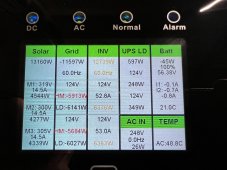
15k. On paper it fit their needs perfectly. 44
SunPower panels at 435. I would have spec’d
It out for two 12ks, but that was way over budget. Now they just want it out. Keep in mind
it was an existing 19.2k grid-tied system that has
been operating flawlessly for months. Now not
only is it not operating as designed but while it
loses production her electric bill is going up.
If I can’t find a remedy soon I’ll be forced to
remove the 15k and battery bank to restore her
SunPower system as it was. Never mind my financial loss, it’s hard to have referrals and any
credibility to her after falling short with no solution. I expected a few bumps with this but
I was up front about anything before the install
began. A few minor concerns have turned this
into an ugly mess with me now communicating
with her attorney. I’ll do whatever it t takes to make it right, that’s how I work, but this one is
really going to sting, no matter the outcome.
I’ve already offered to replace it with 2-12k’s but
they are interested. (I’m covering any additional
costs out of my own pocket)
Anyway, rant over, hopefully SolArk has some
good news for me tomorrow. An exchange unit seems like a good start, if it’s not just a software issue.There are a ton more boring details but I think you heard enough. I’m tired of them asking for the firmware for the Enphase micros. You
aren’t going to convince me they are causing this, not when the inverter is rated for straight
Grid tie without any battery.
 
How about moving a few microinverters over to the the main panel where they can produce.
Leave on SolArk only however many kW it presently works with.
 
Back
Top